AI technical title is built by Patsnap AI team. It summarizes the technical point description of the patent document.
a technology for containers and containers, applied in the field of folding containers, can solve the problems of limited space available in aircraft, waste and cost, easy damage, and often having to be taken out of service for repair, and achieve the effect of improving the stacking characteristics of the collapsed container
Inactive Publication Date: 2010-07-29
TECHNOSEARCH
View PDF11 Cites 5 Cited by
Summary
Abstract
Description
Claims
Application Information
AI Technical Summary
This helps you quickly interpret patents by identifying the three key elements:
Problems solved by technology
Method used
Benefits of technology
Benefits of technology
[0029]In those embodiments which include corners posts, in the collapsed state, the lid lies preferably below the top of the corner posts to improve the stacking characteristics of the collapsed container.
[0041]In a particularly advantageous aspect, the present invention provides a container which can be folded to take up the minimum amount of space for shipping or storage. The container most preferably weighs about the same as or less than existing unit load devices, about 80 Kg, and is constructed so that damaged parts can be replaced relatively easily without taking the container out of service.
Problems solved by technology
There is limited space available in aircraft and air freight containers are typically shaped to make the most of the available space.
One problem with the use of air freight containers is imbalance, which occurs when there are too many containers at one airport and not enough at another.
To correct these imbalances, surplus empty containers have to be shipped to their desired location, which is wasteful and costly particularly when an entire aircraft is filled with empty containers for shipping from one continent to another.
A further problem is maintenance.
Because they are lightly built, they are easily damaged and often have to be taken out of service for repair, typically at least twice a year.
However it is likely that the collapsible container of U.S. Pat. No. 5,941,405 having fabric side walls would not be sufficiently strong for practical commercial use.
U.S. Pat. No. 6,299,009 also discloses a proposed design of collapsible air freight container but which, when collapsed, is not particularly compact.
Method used
Image
Click on the blue label to locate the original text in one second.
Reading with bidirectional positioning of images and text.
Examples
first embodiment
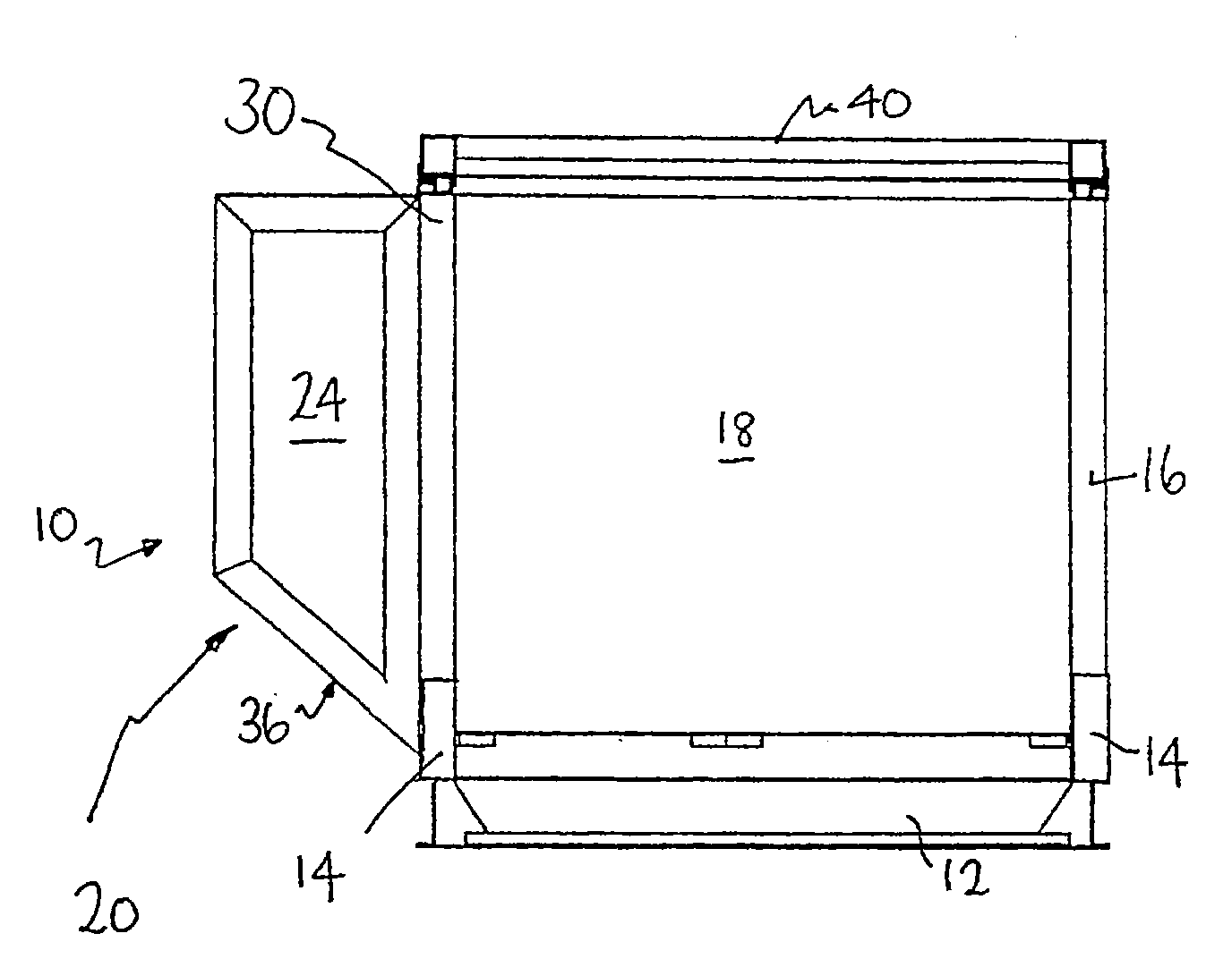
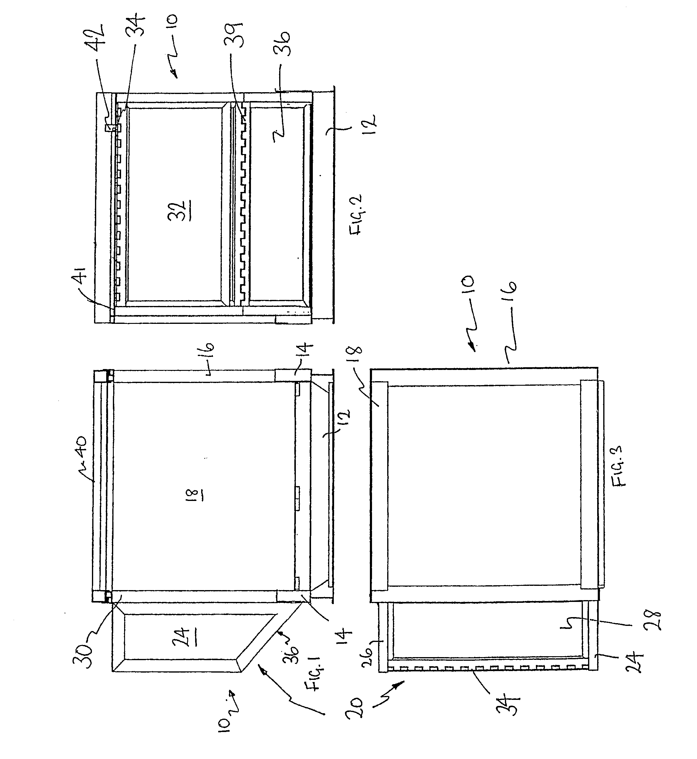
[0050]FIG. 1 is a side elevation of an air freight container embodying the present invention;
[0051]FIG. 2 is a front elevation of the air freight container of FIG. 1;
[0052]FIG. 3 is a top plan view of the air freight container of FIG. 1;
[0053]FIG. 4 is an isometric view of the air freight container of FIG. 1;
[0054]FIG. 5 is a side elevation illustrating a first stage in the folding of the container of FIG. 1;
[0055]FIG. 6 is an isometric view illustrating the first stage in the folding of the container shown in FIG. 5;
[0056]FIG. 7 is a side elevation illustrating a second stage in the folding of the container of FIG. 6;
[0057]FIG. 8 is an isometric view illustrating the second stage in the folding of the container shown in FIG. 7;
[0058]FIG. 9 is an isometric view illustrating a further stage in the folding of the container shown in FIG. 8 being the start of the folding of a side extension;
[0059]FIG. 10 is a further isometric view illustrating the folding of the side extension;
[0060]FI...
second embodiment
[0073]FIG. 24 is a side elevation of an air freight container embodying the present invention;
[0074]FIG. 25 is a front elevation of the air freight container of FIG. 24;
[0075]FIG. 26 is a top plan view of the air freight container of FIG. 24;
[0076]FIG. 27 is an isometric view of the air freight container of FIG. 24;
[0077]FIG. 28 is an isometric view illustrating a first stage in the folding of the container of FIG. 24, being the folding of a side extension;
[0078]FIG. 29 is an isometric view illustrating a second stage in the folding of the side extension of the container shown in FIG. 28;
[0079]FIG. 30 is a side elevation illustrating a third stage in the folding of the side extension of FIG. 29;
[0080]FIG. 31 is an isometric view illustrating a fourth stage in the folding of the side extension shown in FIG. 30;
[0081]FIG. 32 is an isometric view illustrating a further stage in the folding of the side extension shown in FIG. 31.
[0082]FIG. 33 is a side view illustrating a further stage ...
PUM
Abstract
A collapsible air freight container (10) also known as a unit load device, comprises a standard base (12), commonly used on unit load devices, a side panel (16) slideably hinged to the base and a back panel (18) which is hinged to the base which interlocks with the side panel. There is a side extension (20) which is generally trapezoidal to roughly conform to the shape of a side wall of a plane's cargo hold. The side extension (20) includes a frame which (22) is hinged to the base and two trapezoidal (front and rear) panel extensions (24, 26) hinged to the frame. The side extension (20) is completed by a lid (28) and side wall panel (32) connected together by a hinge (34) with the lid (28) being hinged to a top of the frame, and by a sloping bottom panel (36) and relatively short side wall panel (40) hingedly connected to each other with the bottom panel (36) also being hinged to a bottom member of the frame. A lid is slideably mounted on top of the container so that it can be slid relative to the back panel. The lid is arranged so that when fully retracted to the back of the container relative to the back panel, it may pivot to overlay the back panel. As is typical of unit load devices the front of the container is open but may be covered by a flexible curtain or the like. The container may be collapsed by retracting and pivoting the lid to overly the back panel (18), folding the side extension (20) within the frame (22), folding and sliding the side panel (16) into the base (12) and lowering the folded side extension (20) and then the back panel (18) and lid (40) into the base.
Description
CROSS REFERENCE TO RELATED APPLICATIONS[0001]This application is a continuation in part of PCT / AU2008 / 000859 filed on 13 Jun. 2008 (published as WO 2009 / 036484) which claims priority benefit of Australian Provisional Patent Application No. 2007905062 entitled “Improvement in folding container” filed 17 Sep. 2007, the entire contents of all of which are incorporated herein by reference. This application also claims priority benefit of Australian Provisional Patent Application No. 2009905773 entitled “Improvement in folding container” filed 25 Nov. 2009, the entire contents of which are also incorporated herein by reference.FIELD OF THE INVENTION[0002]This invention relates to improvements in folding containers. In particular, it relates to improvements in containers for air transport.BACKGROUND OF THE INVENTION[0003]Air freight containers are used store and transport freight such as packages, perishable goods, mail and the like for loading onto cargo and passenger planes. Such contai...
Claims
Application Information
Patent Timeline
Application Date:The date an application was filed.
Publication Date:The date a patent or application was officially published.
First Publication Date:The earliest publication date of a patent with the same application number.
Issue Date:Publication date of the patent grant document.
PCT Entry Date:The Entry date of PCT National Phase.
Estimated Expiry Date:The statutory expiry date of a patent right according to the Patent Law, and it is the longest term of protection that the patent right can achieve without the termination of the patent right due to other reasons(Term extension factor has been taken into account ).
Invalid Date:Actual expiry date is based on effective date or publication date of legal transaction data of invalid patent.
Patent Type & AuthorityApplications(United States)

