Combustion-type power tool

Inactive Publication Date: 2010-07-29
HITACHI KOKI CO LTD
View PDF20 Cites 14 Cited by
  • Summary
  • Abstract
  • Description
  • Claims
  • Application Information

AI Technical Summary

Benefits of technology

[0006]In view of the foregoing, it is an object of the present invention to provide a combustion-type power tool capable of reliably returning the piston to the initial top dead center.
[0008]It is preferable that the combustion-type power tool further include an exhaust hole and a check valve. The exhaust hole is formed at the cylinder and allows the inner space in communication with an atmosphere. The check valve is disposed in the exhaust port. The check valve is configured to allow air in the inner space to be discharged to outside the cylinder and to prevent air outside the cylinder from flowing into the inner space.

Problems solved by technology

However, in the above-described conventional combustion-type power tool, the piston may not completely return to the initial top dead center when the seal of the check valve degrades or cooling in the upper space is insufficient, making the combustion chamber too large for the next nail driving operation.
When the combustion chamber is too large, the air-fuel mixture produced in the chamber has a low concentration of combustible gas and may not combust, resulting in a failed nail driving operation.

Method used


Image

  • Combustion-type power tool
  • Combustion-type power tool
  • Combustion-type power tool

Examples


Embodiment Construction

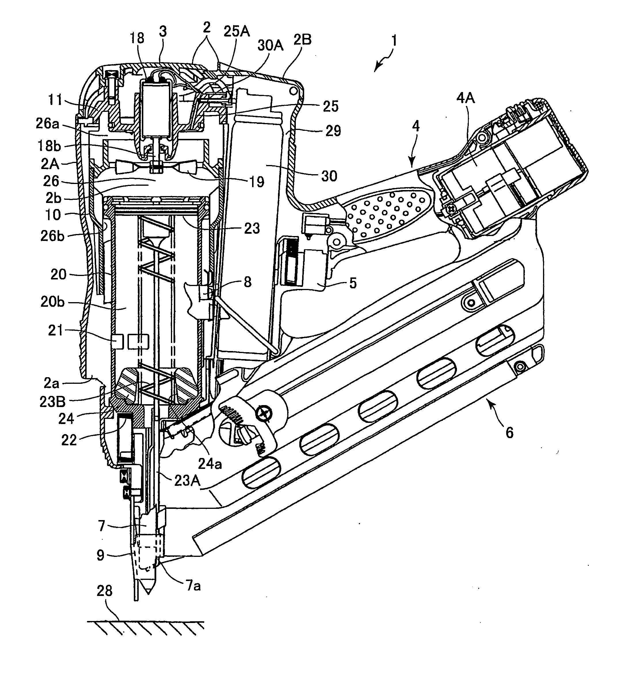
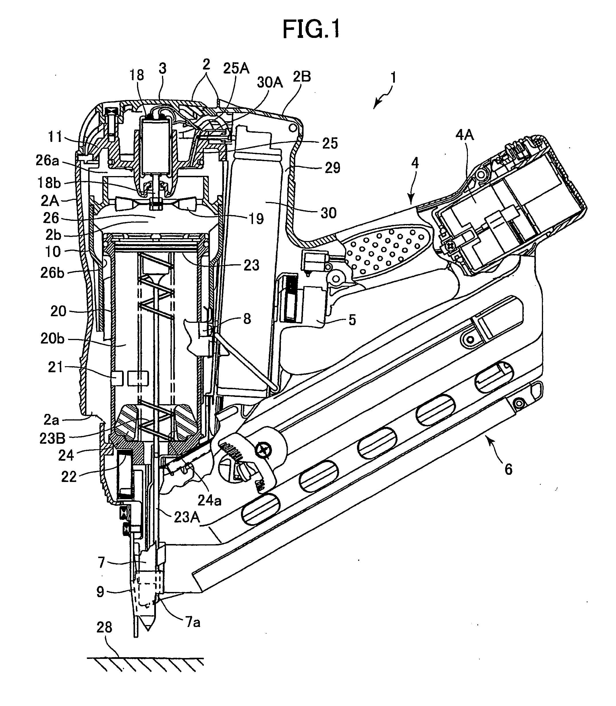
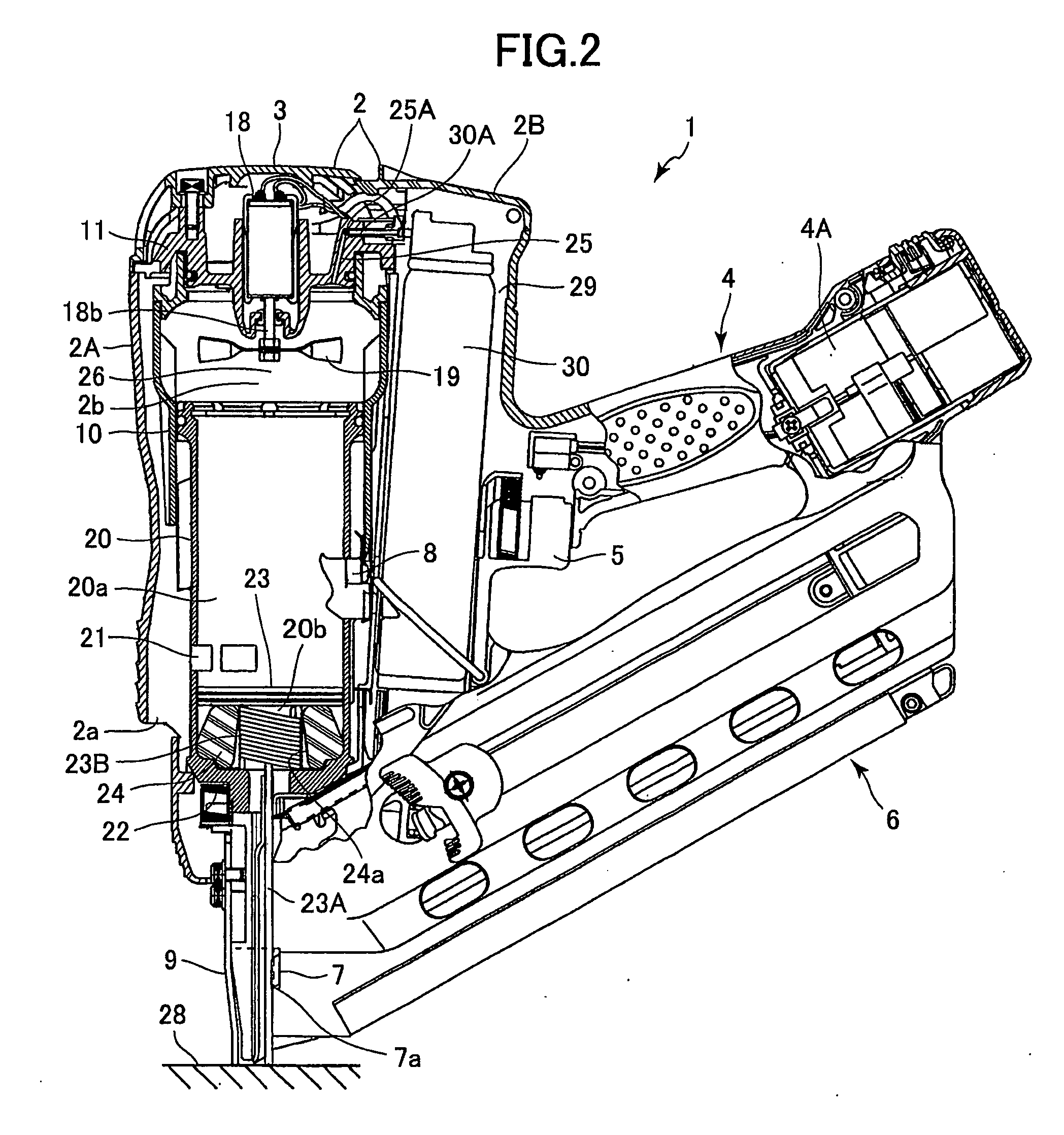
[0037]A combustion-type power tool according to an embodiment of the present invention will be described with reference to FIGS. 1 and 2. The embodiment pertains to a combustion-type nail gun. As shown in FIG. 1, a combustion-type nail gun 1 has a housing 2 constituting an outer frame and including a first housing 2A and a second housing 2B. The first housing 2A extends in a longitudinal direction (axial direction), and has a first end (an upper end in FIGS. 1 and 2) and a second end (a lower end in FIGS. 1 and 2). The first housing 2A is formed with an exhaust port 2a. The second housing 2B is mounted on a side of the first housing 2A. A part of the second housing 2B constitutes a handle 4 which is adapted to be gripped by a user. A head cover 3 having an air inlet (not shown) formed therein is mounted on top of the first housing 2A.

[0038]The handle 4 has a trigger switch 5 and accommodates therein a battery 4A. The battery 4A is detachably disposed in the handle 4. A canister hous...


PUM


Abstract

A combustion-type power tool includes a housing, a cylinder head, a cylinder, a push lever, a piston, a combustion-chamber frame, and an urging member. The cylinder head is disposed at a first end of the housing. The cylinder is disposed in and fixed to the housing. The cylinder has an inner space. The push lever is disposed at a second end of the housing. The piston is slidably disposed in the cylinder and is reciprocally movable in an axial direction. The combustion-chamber frame is disposed in the housing and provides a combustion chamber in cooperation with the cylinder head and the piston. The urging member has one end attached to the piston and another end attached to an axial end of the cylinder, thereby urging the piston in a direction from the second end toward the first end.

Description

TECHNICAL FIELD[0001]The present invention relates to a combustion-type power tool.BACKGROUND ART[0002]Combustion-type power tools such as a nail gun is well known in the art. The power tool ignites a gas mixture containing fuel that is injected into a combustion chamber and translates the volumetric expansion of the gas into power. A combustion-type power tool having this structure includes a housing, a cylinder, and a piston. The housing has first and second ends. The cylinder is fixed in the housing with its axial direction oriented in a direction from the first end to the second end of the housing.[0003]The piston is provided in the cylinder and is capable of slidingly reciprocating relative to the cylinder in the axial direction thereof. The piston divides an inner space of the cylinder into an upper space above the piston and near the first end, and a lower space below the piston and near the second end. A driver blade extends from the piston toward the second end. The driver ...

Claims


Application Information

Patent Timeline
IPC IPC(8): B25C1/08
CPCB25C1/08
Inventor AKIBA, YOSHITAKAMAEHARA, YUKIYOSHI
Owner HITACHI KOKI CO LTD
Why Eureka
Try Eureka