Buggy provided with a braking mechanism

a braking mechanism and buggy technology, applied in the field of buggy, can solve problems such as firm braking action, and achieve the effect of facilitating the movement of the second end

Active Publication Date: 2010-07-29
WONDERLAND NURSERYGOODS CO LTD
View PDF14 Cites 7 Cited by
  • Summary
  • Abstract
  • Description
  • Claims
  • Application Information

AI Technical Summary

Benefits of technology

[0034]According to the preferred embodiment of the buggy, the braking rod further includes an aligning spring arranged to be compressed when the braking rod is moved in the longitudinal direction while the braking rod is not aligned with the recess provided in the wheel. This will result in a proper introduction of the first end of the braking rod when the wheel is slightly moved to align the braking rod and ...

Problems solved by technology

By inserting the first end of the braking rod in a recess provided in the w...

Method used


Image

  • Buggy provided with a braking mechanism
  • Buggy provided with a braking mechanism
  • Buggy provided with a braking mechanism

Examples


Embodiment Construction

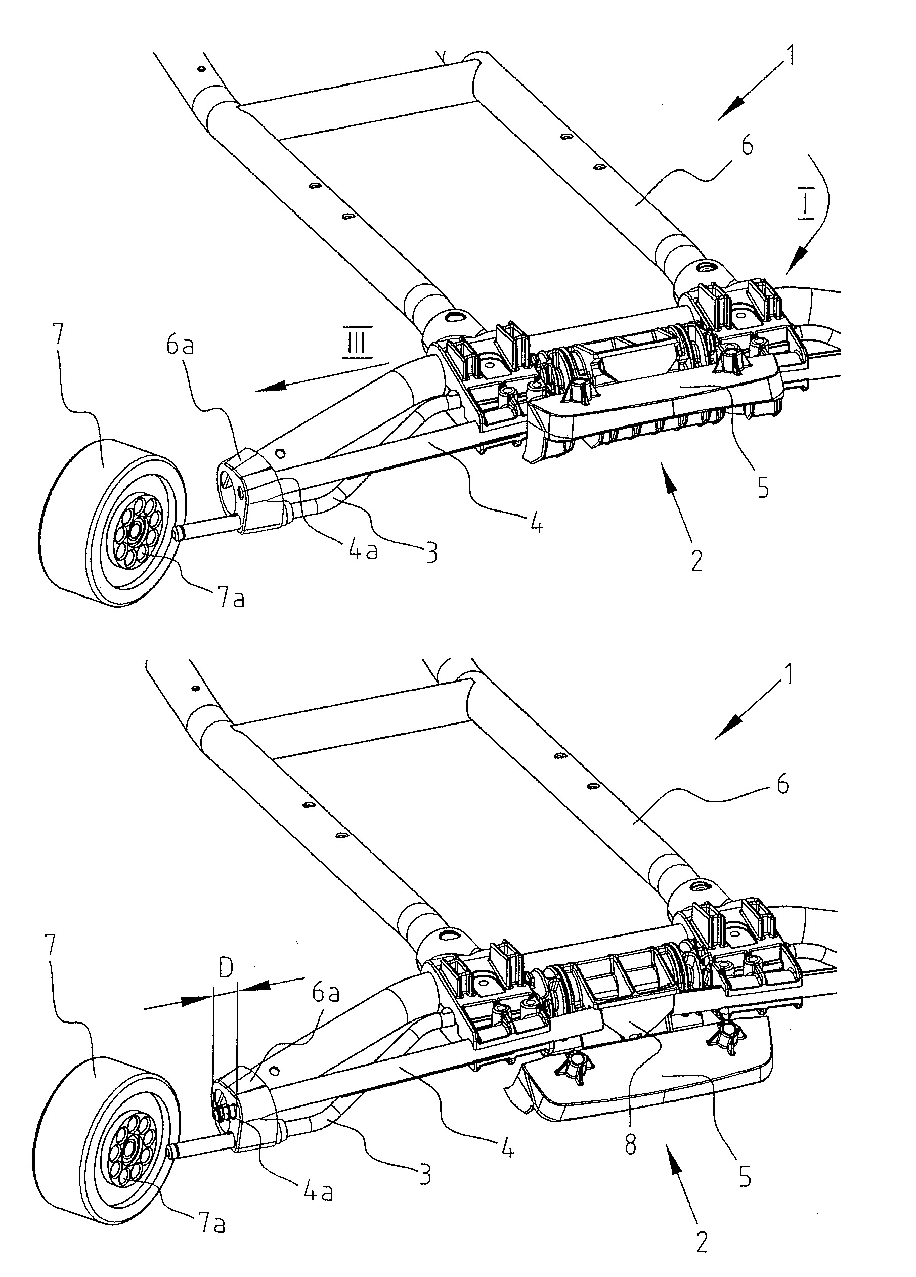
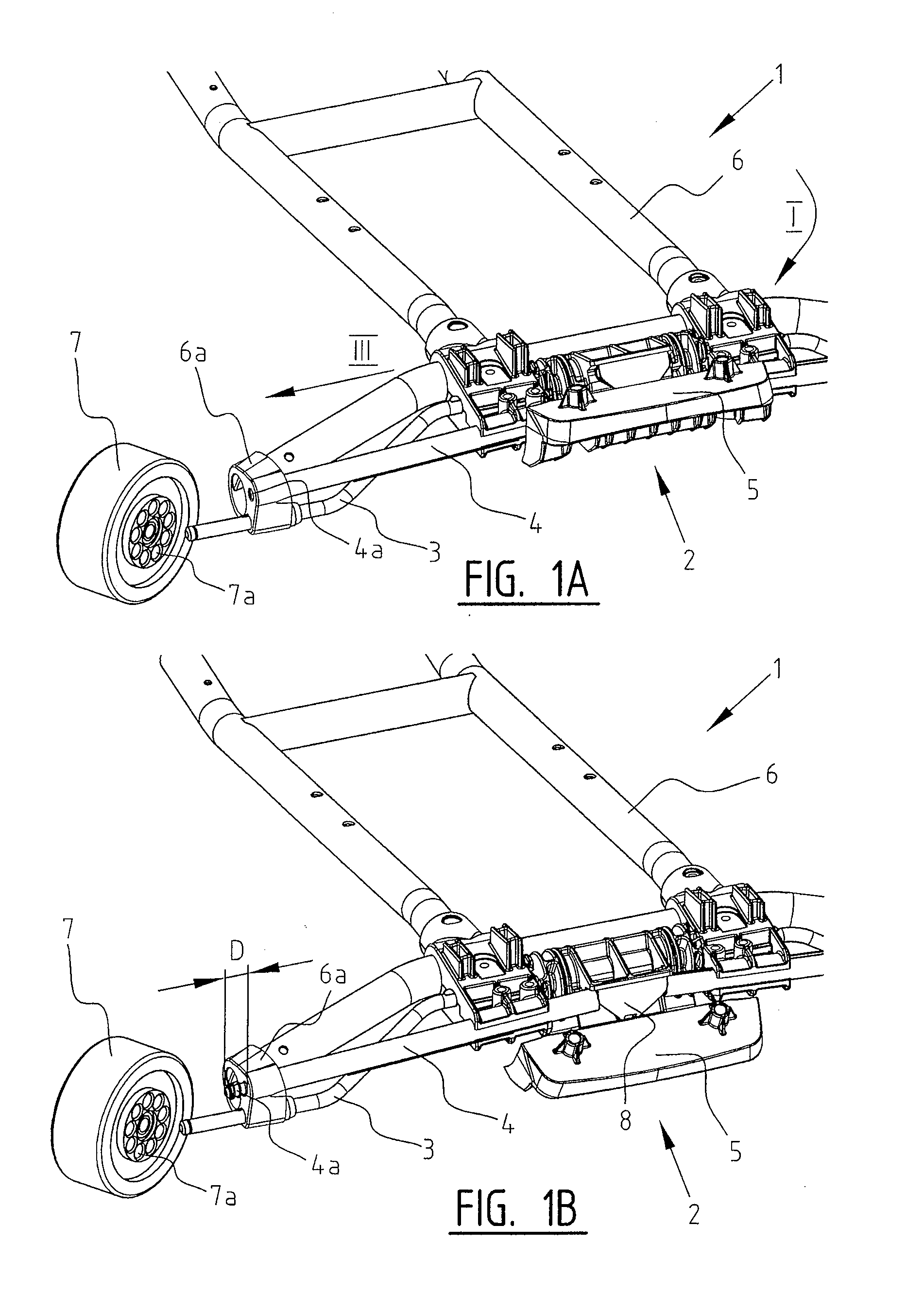
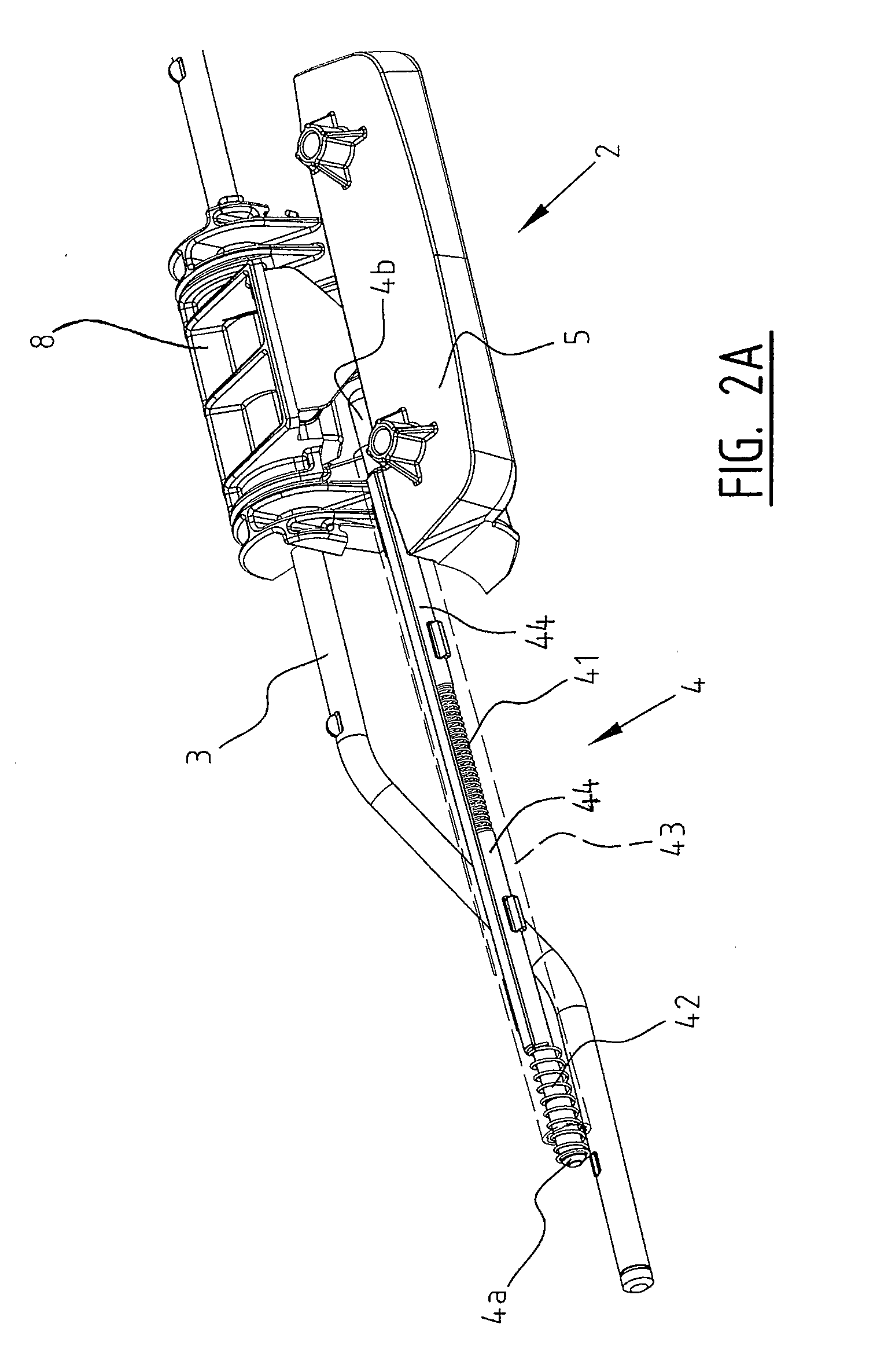
[0048]In FIGS. 9, 1A and 1B, the preferred embodiment of a buggy 1 according to the invention is shown. The buggy 1 comprises a frame 6 on which a seating assembly (not shown) is mounted. The buggy 1 is provided with four wheels coupled rotatably to the frame 6 whereby the rear wheels 7 are provided with a braking mechanism 2. For the sake of clarity, one of the rear wheels 7 is shown in a disconnected state in FIGS. 1A and 1B. The braking mechanism 2 is arranged to be movable between a free position wherein the rear wheels 7 are rotatable around an axle 3, and a braking position wherein the rotations of the rear wheels 7 are limited. For convenience of illustration, only one of the rear wheels 7 will be mentioned in the following description.

[0049]In order to provide an efficient braking mechanism 2, a braking rod 4 is provided to be movable in a third direction (III) indicated in FIG. 1A (i.e., a longitudinal direction). In FIG. 1A, the braking mechanism 2 is at the free position ...


PUM


Abstract

A buggy includes a frame, at least one wheel coupled to the frame and formed with a recess, and a braking mechanism provided to the wheel and including a braking rod that has a first end. The braking mechanism is movable between a free position, where the first end of the braking rod is free from the wheel and the wheel is rotatable, and a braking position, where the first end of the braking rod is received in the recess in the wheel such that the rotation of the wheel is limited.

Description

CROSS-REFERENCE TO RELATED APPLICATION[0001]This application claims priority of U.S. Provisional Application No. 61 / 146,661, filed on Jan. 23, 2009.BACKGROUND OF THE INVENTION[0002]1. Field of the Invention[0003]The present invention relates to a buggy with a frame and at least one wheel provided with a braking mechanism. The braking mechanism is movable between a free position wherein the wheel is rotatable, and a braking position wherein the rotation of the wheel is limited.[0004]2. Description of the Related Art[0005]A buggy or a stroller for transporting a child normally comprises at least three wheels which are interconnected by a frame. The wheels are usually connected to the frame using suitable axles allowing rotation of the wheels with as little friction as possible. A buggy is additionally provided with a seat assembly to comfortably hold the child. A stroller is usually furthermore provided with push bars allowing the stroller to be pushed.[0006]For instance, when placing...

Claims


Application Information

Patent Timeline
IPC IPC(8): B62B7/04
CPCB62B5/04B62B5/0461B62B9/087B62B9/08B62B9/082B62B5/048B62B7/14B62B9/12B62B9/20F16B7/1454B62B7/004B62B5/065
Inventor VAN PETEGEM, FIONABIERMANN, ERICVAN OOSTERUM, SANDERBAAS, ERIKPETERS, AUKJE
Owner WONDERLAND NURSERYGOODS CO LTD
Why Eureka
Try Eureka