Surface Emitting Laser With Hybrid Grating Structure

a laser and surface technology, applied in laser optical resonator construction, laser details, semiconductor lasers, etc., can solve the problems of additional first-order diffracted light output coupling loss, and achieve low critical current value, improve optical coupling efficiency of laser light, and high slope efficiency

Pending Publication Date: 2021-05-13
TRUE LIGHT
View PDF5 Cites 2 Cited by
  • Summary
  • Abstract
  • Description
  • Claims
  • Application Information

AI Technical Summary

Benefits of technology

[0010]The primary objective of the invention is to provide a surface emitting laser with hybrid grating structure and a fabricating method thereof, which integrates the first-order and second-order grating structures to form a hybrid grating structure in the same grating layer, so as to achieve the desired balance between the p

Problems solved by technology

Because that, when the SE-DFB laser formed by the second-order grating structure is in operation, the first-order and the second-order are simultaneously occurred in the optical mode, in addition to the above-mentioned lower efficiency of the second order diffracti

Method used


Image

  • Surface Emitting Laser With Hybrid Grating Structure
  • Surface Emitting Laser With Hybrid Grating Structure
  • Surface Emitting Laser With Hybrid Grating Structure

Examples


Embodiment Construction

[0043]The invention disclosed herein is directed to a surface emitting distributed feedback laser (SE-DFB laser) with a hybrid grating structure and a fabricating method thereof. In the following description, numerous details are set forth in order to provide a thorough understanding of the present invention. It will be appreciated by one skilled in the art that variations of these specific details are possible while still achieving the results of the present invention. In other instance, well-known components are not described in detail in order not to unnecessarily obscure the present invention.

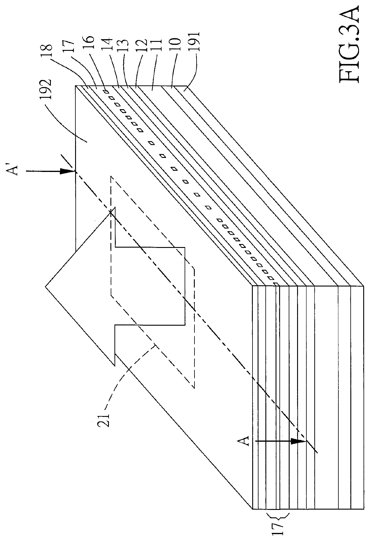
[0044]Please refer to FIG. 3A, FIG. 3B and FIG. 3C, which respectively are a schematic three-dimensional diagram, a schematic cross-sectional diagram, and a schematic top view of grating layer of the first embodiment of the surface emitting distributed feedback laser (SE-DFB laser) with a hybrid grating structure of the present invention. As shown in FIG. 3A, FIG. 3B and FIG. 3C, in the fir...


PUM


Abstract

The grating layer of a surface emitting laser is divided into a first grating region and a second grating region along a horizontal direction. The second grating region is located at a middle area of the grating layer, while the first grating region is located in an outer peripheral area of the grating layer. Each of the first and second grating regions comprises a plurality of micro-grating structures. The grating period of the micro-grating structures in the first grating region is in accordance with the following mathematical formula:
=mλ2*neff;
in addition, the grating period of the micro-grating structures in the second grating region is in accordance with the following mathematical formula:
=oλ2*neff.
Wherein, Λ is the length of grating period, λ is the wavelength of the laser light, neff is the equivalent refractive index of semiconductor waveguide, m=1, and o=2. The first grating region is a first-order grating region, and the second grating region is a second-order grating region, so as to form a hybrid grating structure in the grating layer. The surface emitting laser emits laser light perpendicularly from a light-emitting surface defined by the second grating region.

Description

[0001]This application claims the benefit of Taiwan Patent Application Serial No. 108141251 filed Nov. 13, 2019, the subject matter of which is incorporated herein by reference.BACKGROUND OF INVENTION1. Field of the Invention[0002]The invention relates to a surface emitting laser with hybrid grating structure and a fabricating method thereof, and more particularly to a surface emitting laser having a hybrid grating structure that is divided into two grating regions with different orders of grating periods.2. Description of the Prior Art[0003]Conventionally, the semiconductor laser, or called as the laser diode, is featured in small volume, low power consumption, quick response, well impact resistance, long service life, high efficiency, low price and so on. Thereupon, the semiconductor laser is widely applied to products for electro-optical systems, such as lightwave communications, information systems, household appliances, precision measurements, optical fiber communications and s...

Claims


Application Information

Patent Timeline
IPC IPC(8): H01S5/183H01S5/32H01S5/10
CPCH01S5/183H01S2304/04H01S5/105H01S5/3211H01S5/11H01S5/185H01S5/04254H01S5/34313H01S5/1215H01S5/124H01S5/187
Inventor PAN, CHIEN HUNGWU, CHENG ZU
Owner TRUE LIGHT
Why Eureka
Try Eureka