Conveying and lock system

a technology of applied in the direction of conveying, transportation and packaging, chemistry apparatus and processes, etc., can solve the problems of high cost of both systems and require extensive processing and control technology, and achieve the effect of reliable transport behavior of plastic waste in the conveying and locking system

Inactive Publication Date: 2012-10-09
NILL TECH GMBH
View PDF16 Cites 3 Cited by
  • Summary
  • Abstract
  • Description
  • Claims
  • Application Information

AI Technical Summary

Benefits of technology

[0007]The conveying and lock system in accordance with the invention has the substantial advantage that, in contrast to a double pendulum flap or to a corresponding vane cell lock, the locked chamber or the locked chambers must not be evacuated and no special seals are required to seal the chamber between two pendulum flaps or to seal each individual chamber of the vane cell lock with respect to atmosphere. In the conventional systems, the air is removed from the bulk material being transported by producing a vacuum within the chamber accepting the bulk material. Before the locked chamber is opened with respect to the inner region of the reactor, the conventional system must apply vacuum. In the system in accordance with the instant invention, it is not necessary for a vacuum to be established within the transport screw, since the bulk material is compressed in the winding-free section of the transport screw to generate a bulk material plug. Through establishment of the bulk material plug, the gas located in the bulk material is pressed out and can flow out of the conveying and lock system by way of a gas vent opening.
[0022]In a preferred example of an application, the conveying and lock system can be used to introduce plastic waste as a bulk product into a reactor for the production of high energy fuels, wherein the screw shaft used for this purpose has a compression zone in the transport region of the screw shaft between the inlet and the outlet regions. In the outlet region, the screw shaft can be displaced to different degrees via a plate and the output zone is jacketed by a tube which is separated from the housing of the screw shaft. The tube projects along with the output region into the reactor, wherein only the tube dips into a fluid surface formed within the reactor. Should the tube dip below the fluid surface and should the transport region of the screw shaft in the second winding region be separated from this liquid surface, the tube which surrounds the output region acts as a protective shield to block radiative heat coming from the reaction process of the reactor which then only enters into the conveying and lock system to a limited extent. In this manner, one prevents the plastic waste from already melting in the entrance region to the reactor, which could block the transport system and cause disruption thereof. In this fashion, a proper introduction of the plastic waste into the reactor is guaranteed for long periods of time. The plastic waste is transported from room temperature into a reactor having processing temperatures between 200 degrees and 500 degrees. The plastic waste is introduced into the reactor by means of the conveying and lock system and the plastic waste thereby transported is not warmed above the melting point of the individual plastics. In this manner, reproducible and reliable transport behavior of the plastic waste in the conveying and lock system is guaranteed.

Problems solved by technology

Both systems are expensive and require extensive processing and control technology.

Method used


Image

  • Conveying and lock system
  • Conveying and lock system
  • Conveying and lock system

Examples


Embodiment Construction

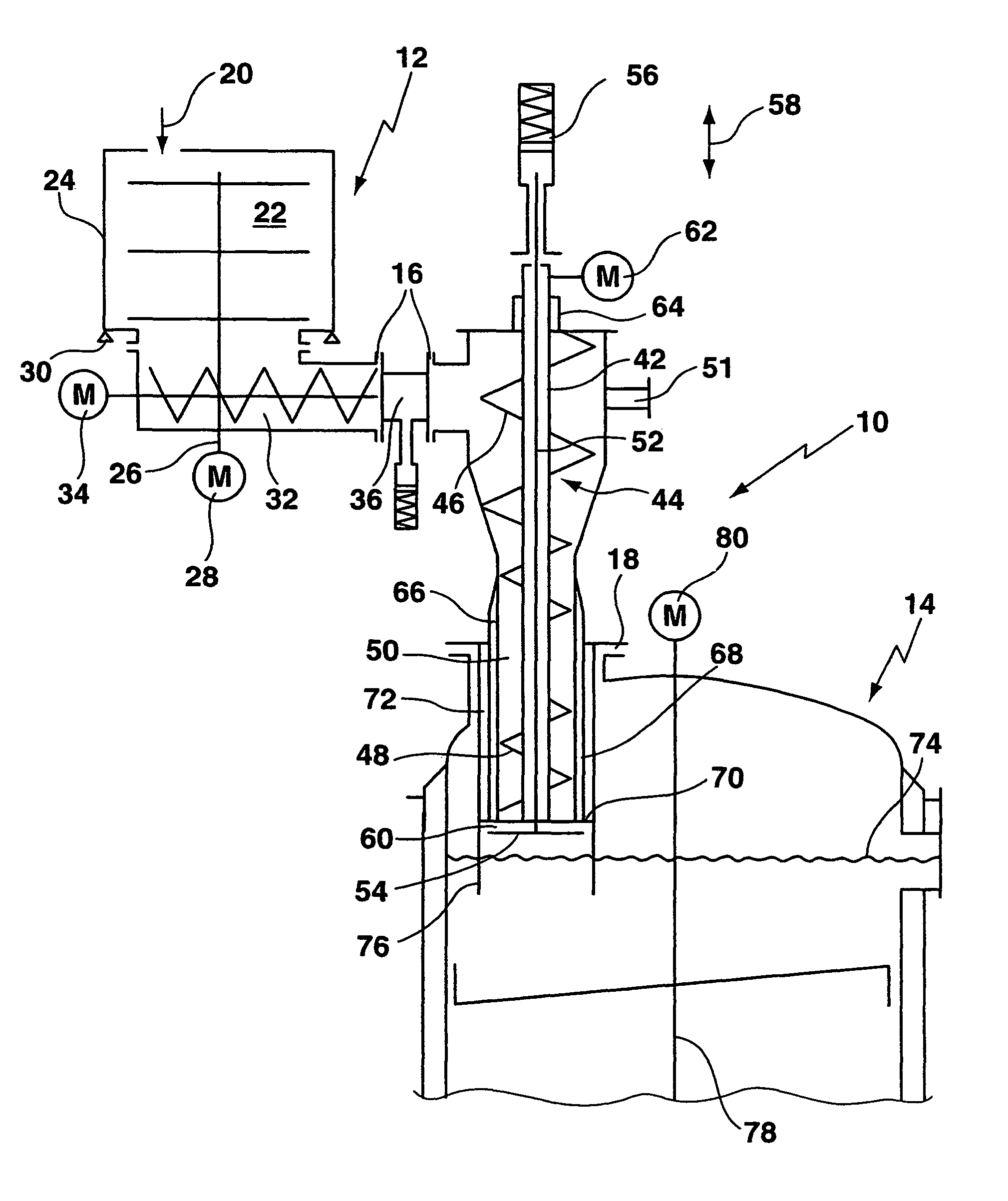
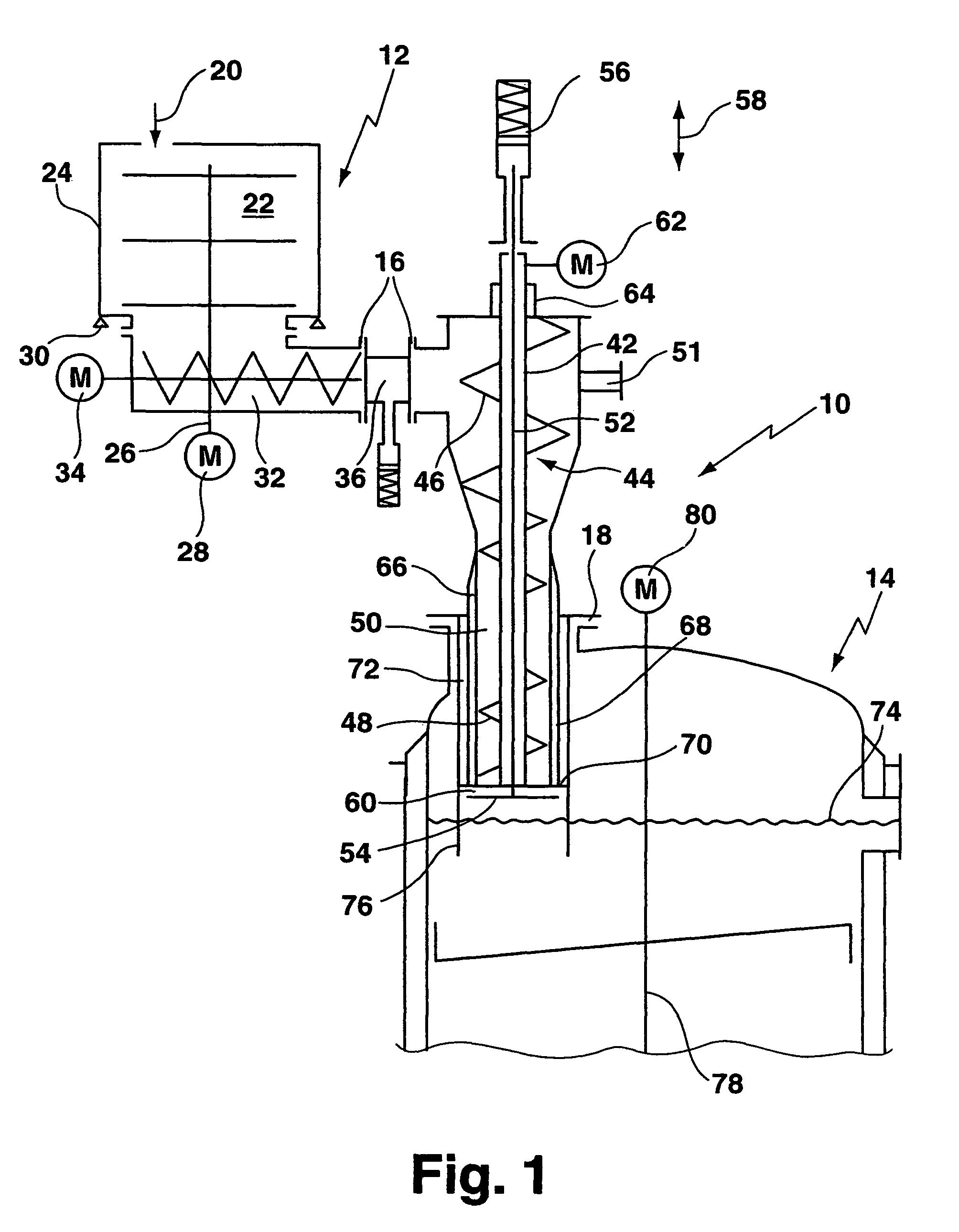
[0026]Reference symbol 10 of FIG. 1 depicts a conveying and lock system which is disposed between a delivery system 12 and a reactor 14. The conveying and lock system 10 is connected to the delivery system 12 as well as to the reactor 14 in a permanent fashion by means of flange connections 16 and 18.

[0027]Plastic particles or plastic waste in the form of bulk material is introduced into an inner region 22 of a storage container 24 in the direction of arrow 20. The bulk material is kept in motion within the storage container 24 by means of a mixer 26 to prevent clumping of the bulk material particles or plastic shred located in the storage container 24. The mixer 26 is driven by a motor 28. The storage container 24 has a weighing device 30 for continuously monitoring delivery to the reactor 14. The weighing device 30 can be used to determine and define the transport capacity of a transfer screw 32 driven by a motor 34. The bulk material located in the storage container 24 is introdu...


PUM


Abstract

A conveying and lock system (10) for introducing a bulk material into a reactor (14) with exclusion of gas and while preventing gas exchange at low pressure differences has a screw shaft (44) on which first windings (46) and second windings (48) are formed. A winding-free section (50) is disposed between the first and the second windings (46, 48) in which the conveyed bulk material is compacted. The compacting causes a bulk material plug which is substantially gas free and, during bulk material transport, the bulk material plug is constantly formed in the conveying and lock system (10) by the screw shaft (44) to prevent gas exchange between the product inlet and the product outlet of the conveying and lock system.

Description

[0001]This application is the national stage of PCT / DE2006 / 002062 filed on Nov. 23, 2006 and also claims Paris Convention priority to DE 10 2005 059 856.0 filed on Dec. 15, 2005.BACKGROUND OF THE INVENTION[0002]The invention concerns a conveying and lock system for introducing bulk material to a reactor, with the exclusion of gas, and while preventing gas exchange at low pressure differences, the system having a housing and a screw shaft disposed therein which is driven to transport the bulk material from an entrance opening to an outlet opening in the housing.[0003]In a plurality of preparation processes involving bulk materials, it is either desirable or technically necessary that the process takes place without or substantially without air in order to be able to achieve the desired purpose or such that the amount of air transported along with the bulk material is reduced to a minimum before the bulk material is subject to further processing. An example thereof are processes with ...

Claims


Application Information

Patent Timeline
Patent Type & Authority Patents(United States)
IPC IPC(8): B65G25/00
CPCB01J8/003B01J8/0045B65G53/48C10G1/10B01J2208/00752B01J2208/00769
Inventor NILL, EBERHARDSCHMILLEN, ANTON
Owner NILL TECH GMBH
Why Eureka
Try Eureka