Tubular Torsion Beam for Rear Suspensions of Vehicles and Manufacturing Method Thereof

a technology for rear suspensions and tubular torsion beams, which is applied in resilient suspensions, interconnection systems, metal-working apparatuses, etc., can solve the problems of increasing the weight of a final product, affecting the stability of the vehicle, and complicating the production process of the beam, so as to improve the roll stiffness and roll strength of the tubular torsion beam, and increase the thickness of a stress-concentrated portion. , the effect of high durability

Active Publication Date: 2010-07-29
POHANG IRON & STEEL CO LTD
View PDF12 Cites 31 Cited by
  • Summary
  • Abstract
  • Description
  • Claims
  • Application Information

AI Technical Summary

Benefits of technology

[0020]The tubular torsion beam for rear suspensions of vehicles and the method of manufacturing the tubular torsion beam according to the present invention are advantageous in that the roll stiffness and roll strength of

Problems solved by technology

Deformations or cracks formed in the suspensions may impose fatal effects on vehicle stability, and thus the durability design of the suspensions plays an important role in the functional design of the suspensions.
However, due to the reinforcement, the plate-type torsion beam 3 is problematic in that the increased number of elements constitutes the beam 3, complicates the production process of the beam 3, and increases the weight of a final product.
However, the conventional pr

Method used


Image

  • Tubular Torsion Beam for Rear Suspensions of Vehicles and Manufacturing Method Thereof
  • Tubular Torsion Beam for Rear Suspensions of Vehicles and Manufacturing Method Thereof
  • Tubular Torsion Beam for Rear Suspensions of Vehicles and Manufacturing Method Thereof

Examples


first embodiment

[0056]According to the present invention, a design for a durable tubular torsion beam, which can increase the roll stiffness of the torsion beam and can reduce the roll strength thereof, based on the above-mentioned stress distribution, thus realizing excellent durability of the torsion beam, can be provided.

[0057]Described in detail, as shown in FIG. 7(a), the thickness T of each of the opposite ends 11, which has higher roll strength in the tubular torsion beam 10, is increased to be higher than the thickness t of the middle portion. Further, as shown in FIG. 7(b), a bead 14 is formed on the surface of the transitional portion 12, at which the maximum stress acts. The bead 14 may be exclusively formed on the transitional portion 12, at which the maximum stress acts, or may be formed so as to extend from the transitional portion 12 to each of the opposite ends 11.

[0058]To measure the effects of the above-mentioned durable design, roll stiffness and roll strength are measured using ...

second embodiment

[0066]Meanwhile, according to the present invention, a durable design capable of improving the durability of a tubular torsion beam 10 by reinforcing the lower part of each transitional portion, in which maximum stress (roll strength) acts, as shown in FIG. 6, can be provided.

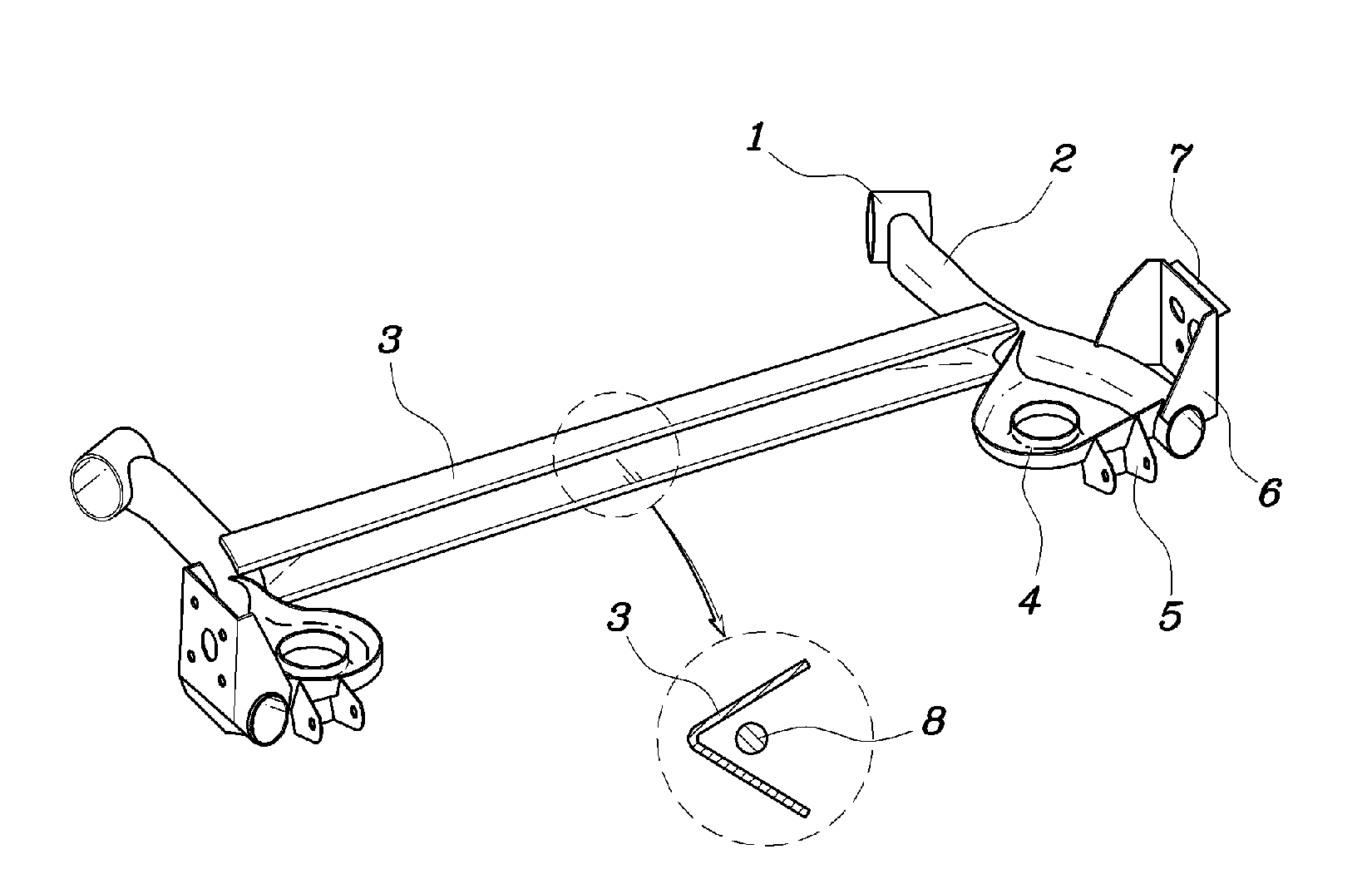
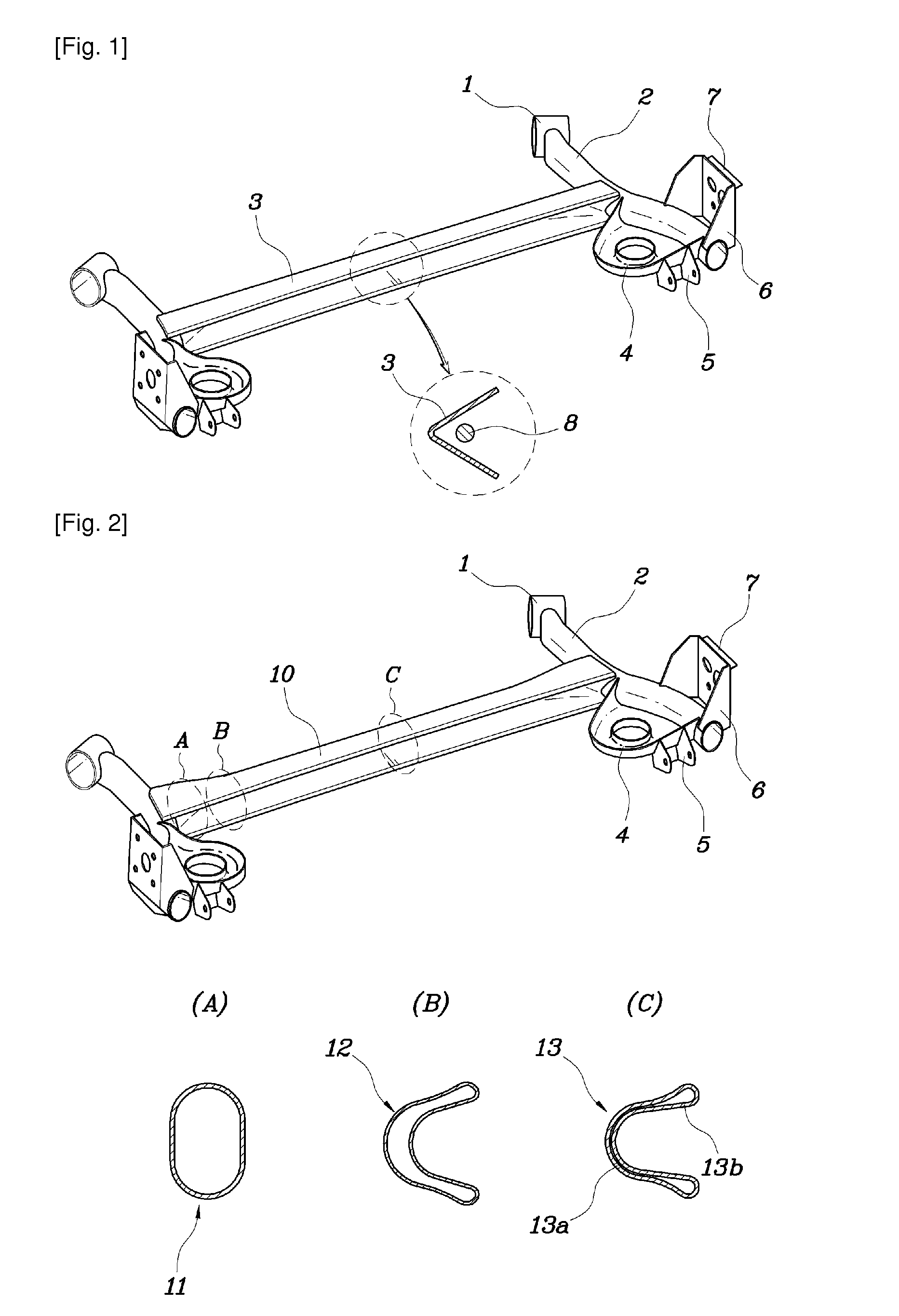
[0067]Described in detail, as shown in FIG. 8, in a tubular torsion beam 10 produced by pressure-forming a tubular steel member through hydroforming such that the torsion beam 10 has a cross-section varying along the entire length thereof, with opposite ends 11 having a closed cross-section and mounted to respective trailing arms 2, a middle portion 13 having a V-shaped open cross-section, and a transitional portion 12 having a varying cross-section and connecting the middle portion 13 to each of the opposite ends 11 while executing a natural transition from the middle portion to the opposite end, an inclined offset 15 is formed between the middle portion 13 and each of the transitional portions 12, so that bot...


PUM

PropertyMeasurementUnit
Fractionaaaaaaaaaa
Widthaaaaaaaaaa
Widthaaaaaaaaaa

Abstract

Provided is a tubular torsion beam for rear suspensions of vehicles, which is produced according to a more durable design capable of improving roll stiffness and roll strength of the tubular torsion beam. The tubular torsion beam is produced by pressure-forming a tubular steel member through hydroforming such that the tubular torsion beam has a cross-section varying along an entire length thereof, with opposite ends having a closed cross-section and mounted to respective trailing arms, a middle portion having a V-shaped open cross-section, and a transitional portion having a varying cross-section and connecting the middle portion to each of the opposite ends. During the process of manufacturing the tubular torsion beam, the opposite ends of the tubular steel member are fed using respective axial punches of a hydroforming machine, so that the opposite ends are thicker than the middle portion.

Description

TECHNICAL FIELD[0001]The present invention relates, in general, to a tubular torsion beam for rear suspensions of vehicles and a manufacturing method thereof and, more particularly, to the provision of tubular torsion beams having excellent roll stiffness and excellent roll strength, produced through hydroforming.BACKGROUND ART[0002]Suspensions for vehicles are structural devices used for suspending a vehicle body and absorbing shocks from the road during the operation of a vehicle, thereby preventing the shocks from being applied to the vehicle body and to passengers. Thus, the suspensions must be designed such that they can attenuate shocks from a road and make passengers feel comfortable despite the shocks, and improve steering stability, determined by the ground contact force of tires during running of vehicles. Another important factor to be considered while designing suspensions is that the suspensions must maintain desired stiffness and desired durability despite the repeated...

Claims


Application Information

Patent Timeline
IPC IPC(8): B60G21/05B21D53/88
CPCB60G21/051B60G2200/23Y10T29/49622B60G2206/8107B60G2206/202B60G11/00B60G11/18
Inventor CHOI, HAN HOKANG, YEON SIKPARK, SUNG HOOH, JIN HOKIM, KEUN HWAN
Owner POHANG IRON & STEEL CO LTD
Why Eureka
Try Eureka