Vehicle structure

a technology for vehicles and structures, applied in the field of vehicles, can solve the problems of insufficient absorption of excessive load (energy), side members, etc., and achieve the effects of reducing load, reducing movement, and increasing reaction for

Inactive Publication Date: 2010-07-29
TOYOTA JIDOSHA KK
View PDF0 Cites 59 Cited by
  • Summary
  • Abstract
  • Description
  • Claims
  • Application Information

AI Technical Summary

Benefits of technology

[0007]Thus, the object of the invention is to provide a vehicle structure which suppresses the relative movement between a floor tunnel and structural members on both sides thereof, and disperses a large load, in a case where the large load is input to a floor tunnel.
[0009]In this vehicle structure, the floor tunnel is reinforced by the tunnel reinforcing members, and the tunnel reinforcing members, and the members extending in a direction including a vehicle longitudinal component outside the reinforcing members are combined together by the supporting frame. In a case where a large load is input to the floor tunnel due to a pole frontal collision, an offset frontal collision, etc., in this vehicle structure, the load is transmitted to the supporting frame via the tunnel reinforcing members, and the transmitted load is further transmitted to the members extending in a direction including a vehicle longitudinal component via the supporting frame. This enables the input load to the floor tunnel to be dispersed to the members extending in a direction including a vehicle longitudinal component from the tunnel reinforcing members, and enables a reaction force to be generated in each of the tunnel reinforcing members and the members extending in a direction including a vehicle longitudinal component against each dispersed load. Moreover, in this vehicle structure, the supporting frame suppresses the rearward movement of the floor tunnel caused by the input load, suppresses the forward movement of the members extending in a direction including a vehicle longitudinal component, and suppresses the relative movement between the floor tunnel and the members extending in a direction including a vehicle longitudinal component. As a result, a large reaction force can be generated against the large load to the floor tunnel, and deformation of a passenger cabin can be suppressed as much as possible.
[0012]In this vehicle structure, the tunnel reinforcing members, the side members outside the tunnel reinforcing members, and side sills outside the side members are combined together by the supporting frame. In a case where a large load is input to the floor tunnel, in this vehicle structure, the load is transmitted to the supporting frame via the tunnel reinforcing members, and the transmitted load is also transmitted to the side sills outside the side members other than the side members via the supporting frame. This enables a large input load to the floor tunnel to be dispersed to the side members and the side sills from the tunnel reinforcing members, and enables a reaction force to be generated in each of the tunnel reinforcing members, the side members, and the side sills against each dispersed load. Moreover, in this vehicle structure, the supporting frame suppresses the rearward movement of the floor tunnel caused by the input load, suppresses the forward movement of the side members and side sills, and suppresses the relative movement between the floor tunnel and the side members and side sills. Additionally, it is even possible to suppress the movement such that the side sills tend to come out in a forward direction relative to the side members. As a result, load can be further dispersed, a larger reaction force can be generated against input load, and local transformation can be suppressed.
[0013]In the above vehicle structure of the invention, it is preferable that the supporting frame is arranged at a front end of the floor tunnel. As the supporting frame is located closer to the front end, the tunnel reinforcing members for transmitting load to the supporting frame can be shortened, and mass can be reduced.

Problems solved by technology

In the case of pole (power pole, etc.) frontal collision against a limited region in the vicinity of one side or center of a front surface of a vehicle, or an offset frontal collision, due to transverse folding of a crash box, front side members, etc., EA (Energy Absorption) structural members (front side members, etc.) for absorbing energy ahead of the passenger cabin cannot function effectively compared with a full wrap frontal collision, and cannot sufficiently absorb the excessive load (energy) caused by collision.
Thus, if the tunnel reinforcements are provided throughout the tunnel portion in a case where it is considered that the proof stress of the tunnel reinforcements is greatly improved, a large increase in mass is caused.
Additionally, if the tunnel reinforcements are provided only at the portions of the tunnel portion ahead of the passenger cabin, there is a possibility that transverse folding may be caused on the boundary between a strong strength portion and a weak strength portion due to an excessive load.

Method used


Image

  • Vehicle structure
  • Vehicle structure
  • Vehicle structure

Examples


first embodiment

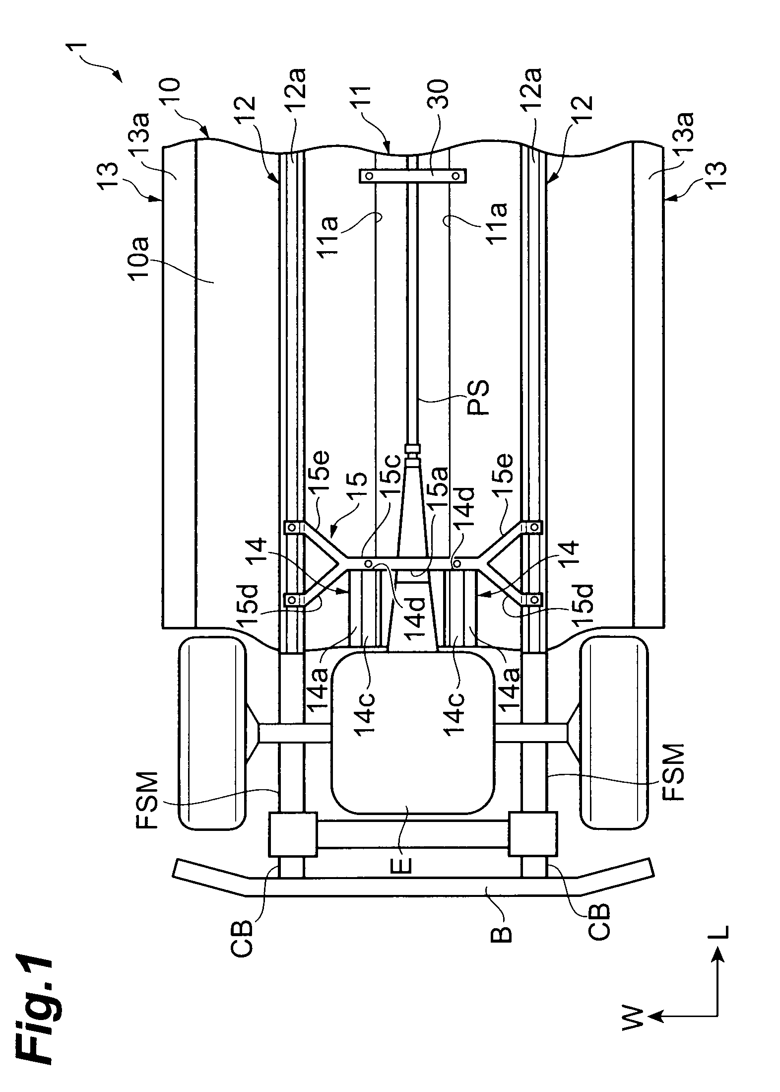
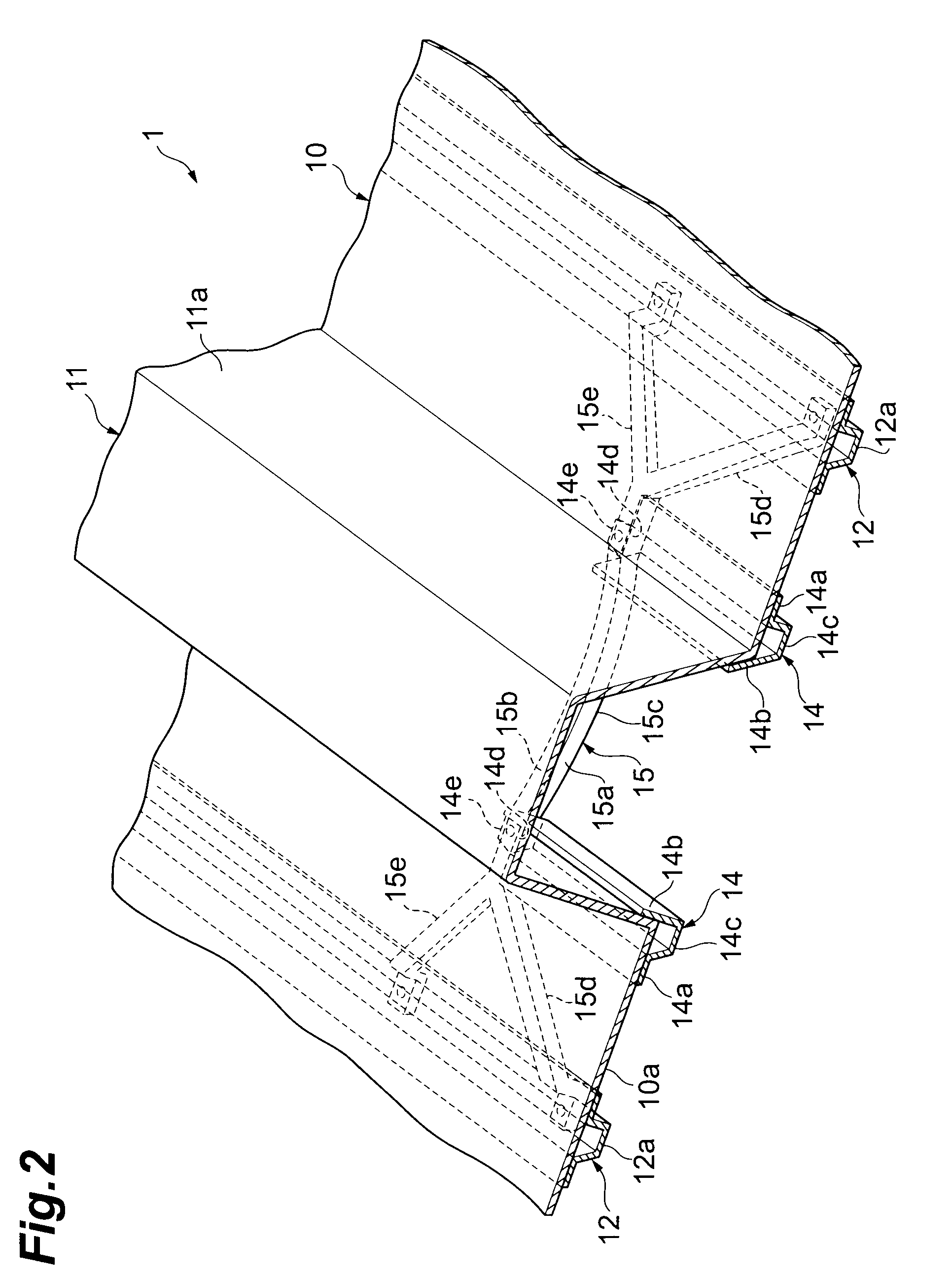
[0024]Moreover, the underbody structure 1 includes a pair of right and left tunnel reinforcements 14 and 14 of one pair of right and left, and a supporting frame 15. In addition, in the first embodiment, each tunnel reinforcement 14 corresponds to each tunnel reinforcing member set forth in the Claims, and the supporting frame 15 corresponds to the supporting frame set forth in the Claims.

[0025]The tunnel reinforcement 14 is arranged to a position which touches the supporting frame 15 from a front end of the tunnel portion 11 in the vehicle longitudinal direction (L), and is disposed at an undersurface 10a of the floor 10 at an outer edge of the tunnel portion in the vehicle width direction (W). That is, the tunnel reinforcement 14 is provided at a corner formed by an inner surface of a side wall 11a of the tunnel portion 11, and the undersurface 10a of the floor 10. The tunnel reinforcement 14 has a convex shape which protrudes downward from the floor 10 in the vehicle height direc...

second embodiment

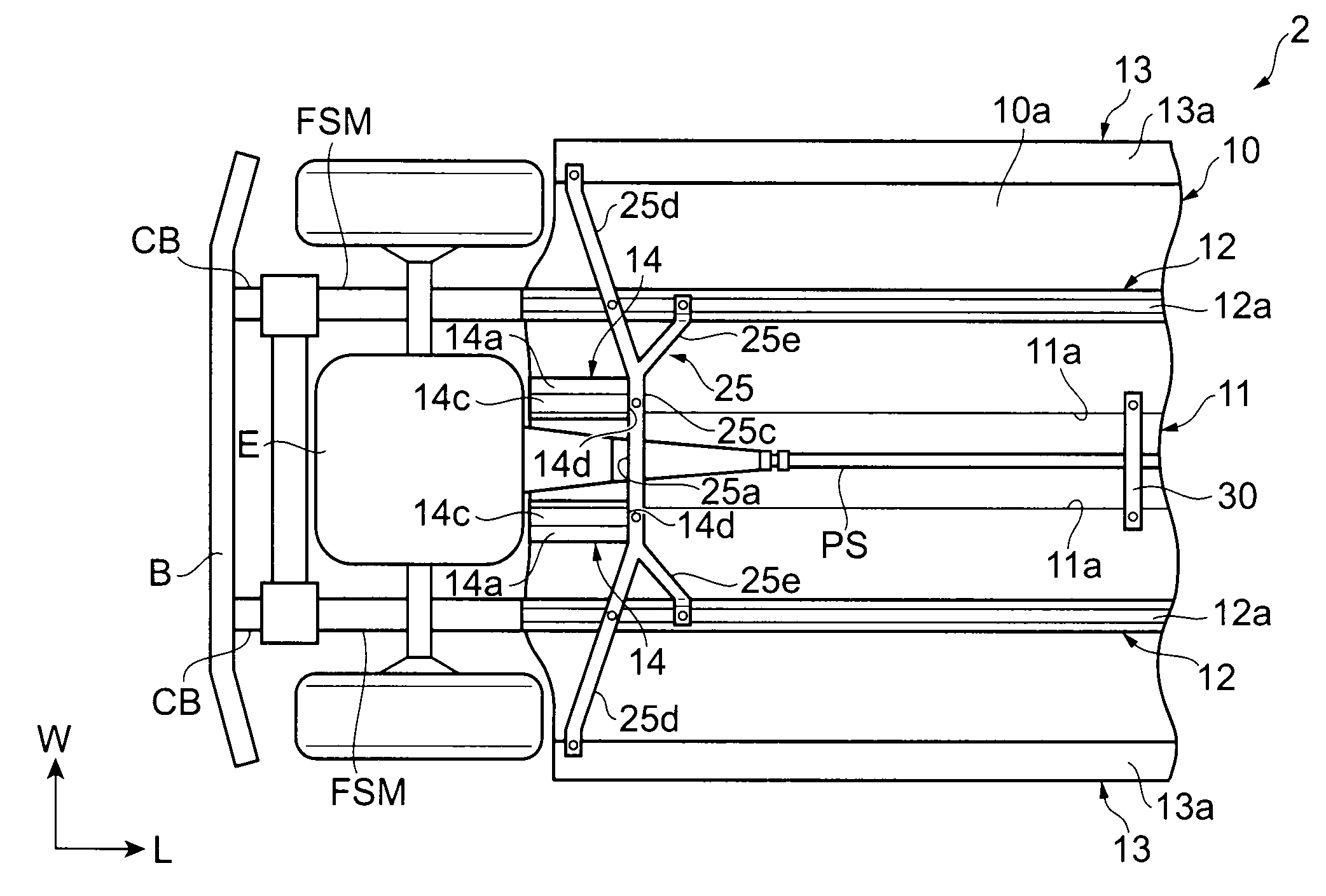
[0039]The underbody structure 2 is different in the shape of the supporting frame 25 and the combined destination of the supporting frame 25 as compared with the underbody structure 1. In addition, in the second embodiment, the supporting frame 25 corresponds to the supporting frame set forth in the Claims.

[0040]The supporting frame 25 is arranged at the front end of the tunnel portion 11 in the vehicle longitudinal direction (L), and is arranged between right and left sills 13 and 13 in the vehicle width direction (W). The supporting frame 25, similarly to the supporting frame 15 according to the first embodiment, includes a trunk portion 25c, and right and left front leg portions 25d and 25d and rear leg portions 25e and 25e, and is substantially X-shaped (in plan view). The supporting frame 25 is different from the supporting frame 15 only in the shape of the front leg portion 25d.

[0041]The front leg portion 25d has a quadrangular prismatic shape, and its distal end has a shape ...


PUM


Abstract

A vehicle structure including a floor tunnel includes: tunnel reinforcing members for reinforcing at least a front portion of the floor tunnel; and a supporting frame combined with the tunnel reinforcing members and side members or a supporting frame combined with the tunnel reinforcing members, the side members, and side sills. The supporting frame is preferably arranged at a front end of the floor tunnel.

Description

TECHNICAL FIELD[0001]The present invention relates to a vehicle structure having a floor tunnel.BACKGROUND ART[0002]A pair of right and left side sills which extend from front side members within an engine room, a pair of right and left side members arranged outside the side sills, etc. are disposed as structural members on the floor of a vehicle body. In order to dispose a propeller shaft, etc. especially in the case of a rear drive vehicle, etc., a floor tunnel which extends in a vehicle longitudinal direction is provided at the center of the floor in a vehicle width direction. Tunnel reinforcements for reinforcing a tunnel portion independently from other surrounding structural members are disposed at the floor tunnel. Additionally, in a vehicle structure described in Patent Citation 1, a tunnel cross member which connects right and left side members is disposed, and a pair of floor cross members which are linearly joined to the tunnel cross member, and connect the side members a...

Claims


Application Information

Patent Timeline
Patent Type & Authority Applications(United States)
IPC IPC(8): B62D25/20
CPCB62D25/20B62D21/09
Inventor TSUCHIDA, TAKUJI
Owner TOYOTA JIDOSHA KK
Why Eureka
Try Eureka