

Data cartridge device for computer equipment
- Summary
- Abstract
- Description
- Claims
- Application Information
AI Technical Summary
Benefits of technology
Problems solved by technology
Method used
Image

Examples
Embodiment Construction
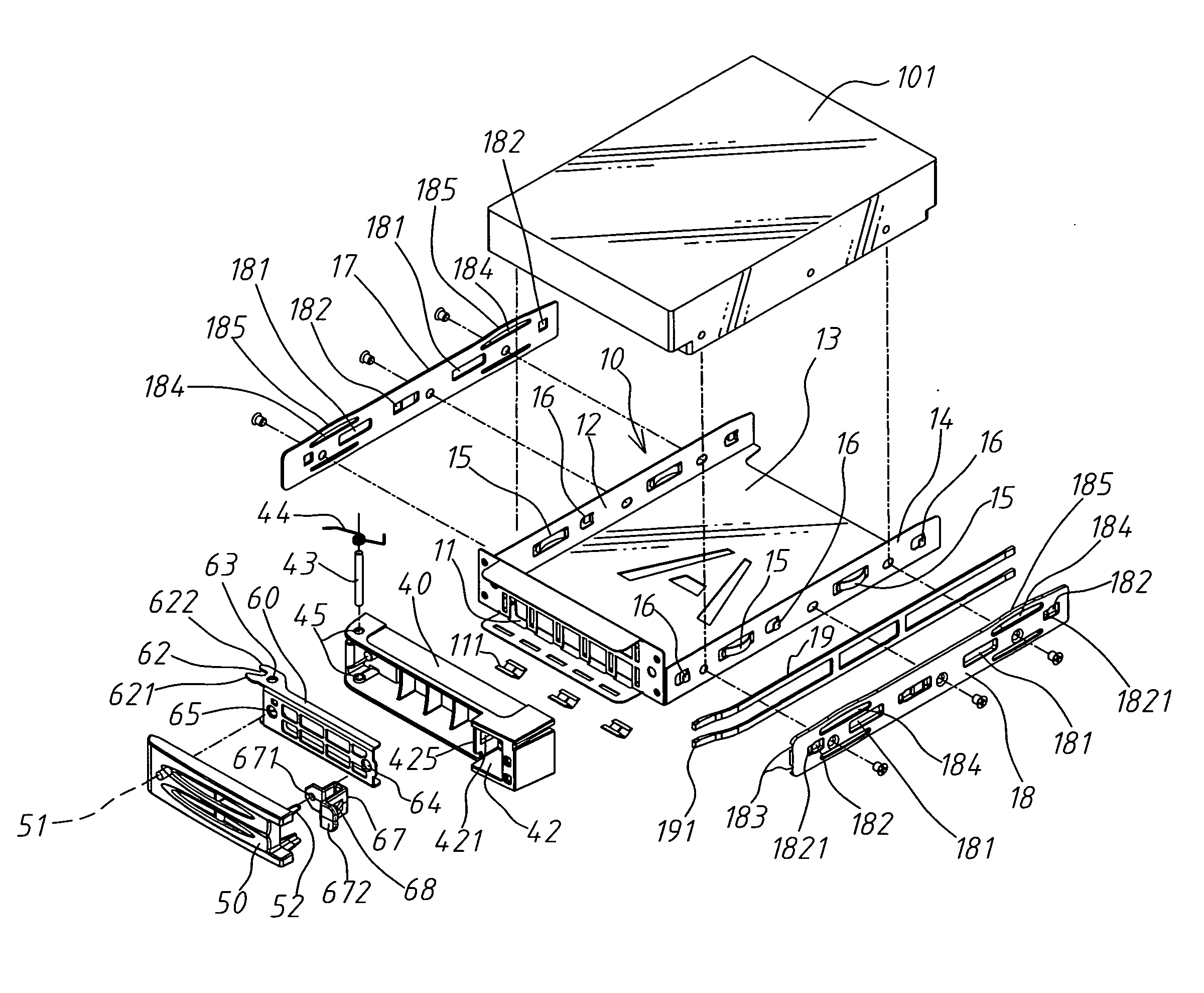
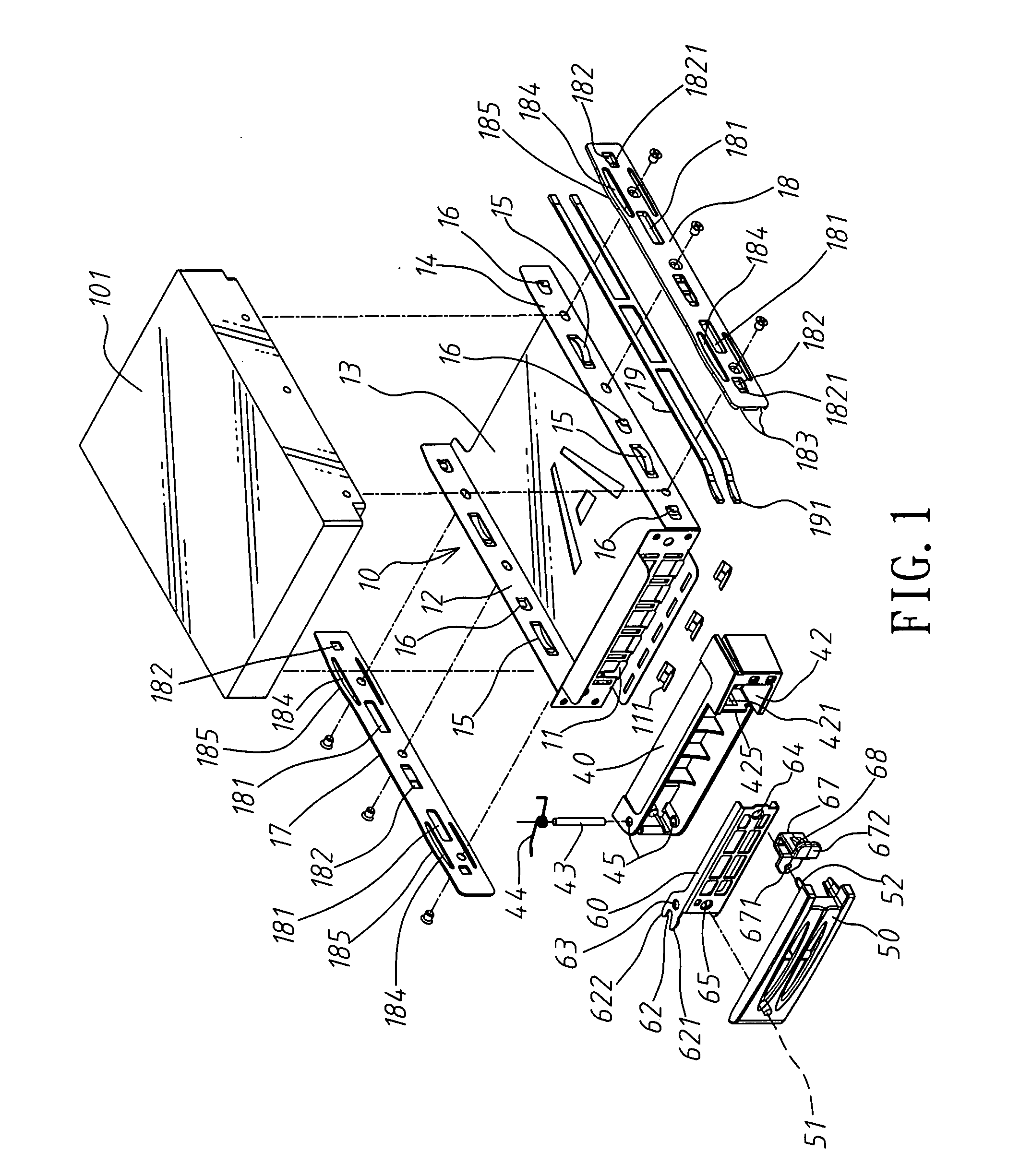
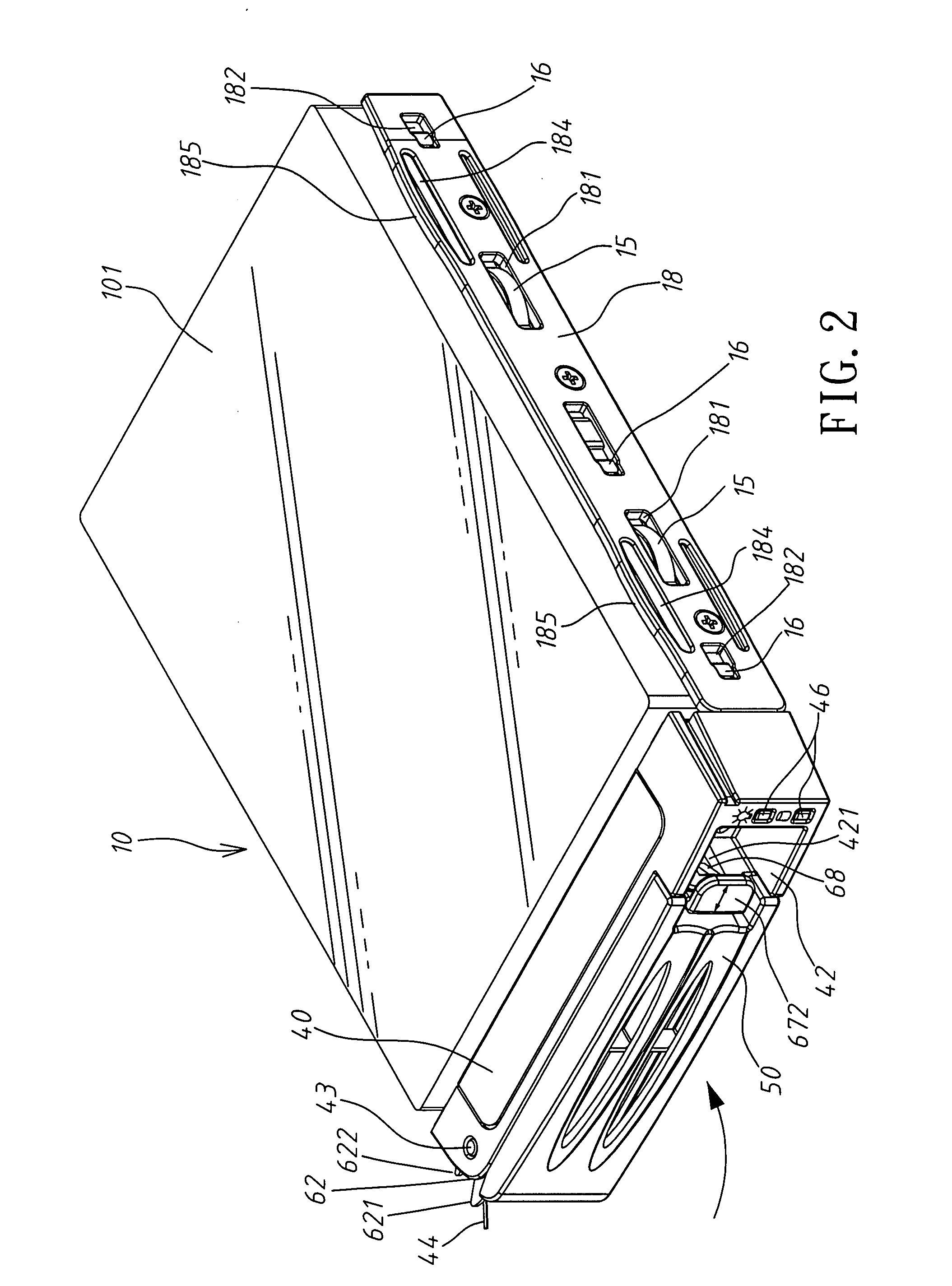
[0022]Referring to FIG. 1, the present invention is to provide a data cartridge device for computer equipment, including a data cartridge 10, which is provided with a left wall 12 and a right wall 14, and an interior of which is provided with a containing space 13, with outer surfaces of the left and right walls 12, 14 being disposed respectively with arc-shape spring leaves 15 and hooks 16 that are protruded outward; a left board 17 and a right board 18, which are screwed and fixed respectively on the outer surfaces of the left and right walls 12, 14, and central positions of which are provided with at least one long through-hole 181 out of which being protruded by the arc-shape spring leaf 15, with a side of the long through-hole 181 being disposed with at least one positioning hole 182, an edge of the positioning hole 182 being disposed with a locking interface 1821 that is concaved inward, the hook 16 being transfixed out of the positioning hole 182 and being hooked at the locki...
PUM
 Abstract
Description
Claims
Application Information