Stroke sensor and rotation angle sensor

a technology of stroke sensor and rotation angle, which is applied in the direction of galvano-magnetic hall-effect devices, electrical control, instruments, etc., can solve the problem that the correlation between the stroke amount and the output value cannot become an ideal linear characteristic, the sensing accuracy cannot improve more than the limit, and the effect of accurate output value and accurate output valu

Active Publication Date: 2010-07-29
DENSO CORP
View PDF8 Cites 28 Cited by
  • Summary
  • Abstract
  • Description
  • Claims
  • Application Information

AI Technical Summary

Benefits of technology

[0060]Therefore, concerning the sensing of each of the angle of the integral multiple of 360° (or stroke amount generated by converting rotation angle) and the angle equal to or smaller than 360°, like the fourth example aspect of the present invention, the S/N ratio with respect to each of the output values can be improv...

Problems solved by technology

Therefore, sensing accuracy of the stroke sensor and the rotation angle sensor cannot be improved more than a limit based on the temperature characteristics.
Therefore, in the stroke sensor, a correlation between the stroke amount and the output value does not become an ideal linear characteristic.
However, ...

Method used


Image

  • Stroke sensor and rotation angle sensor
  • Stroke sensor and rotation angle sensor
  • Stroke sensor and rotation angle sensor

Examples


first embodiment

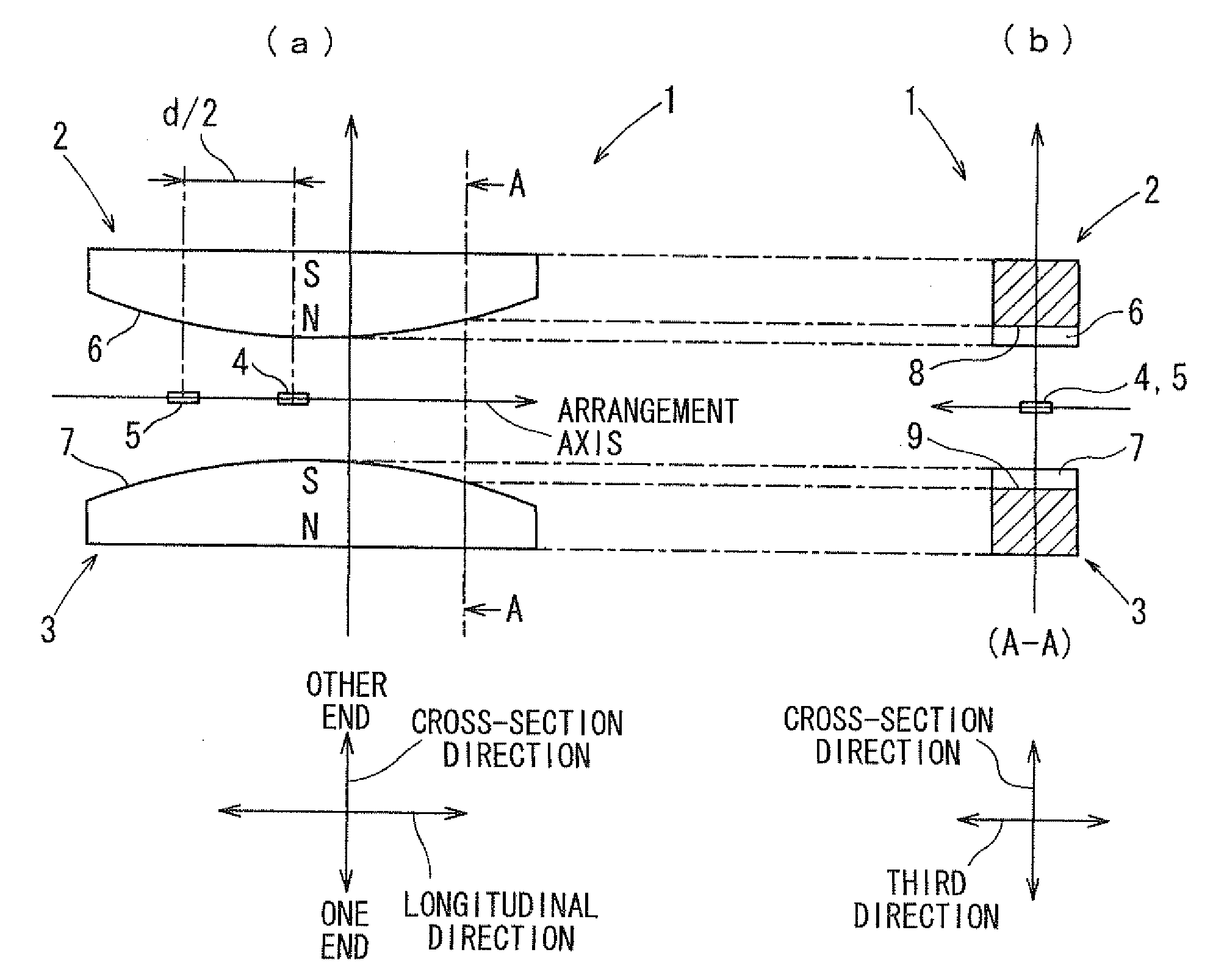
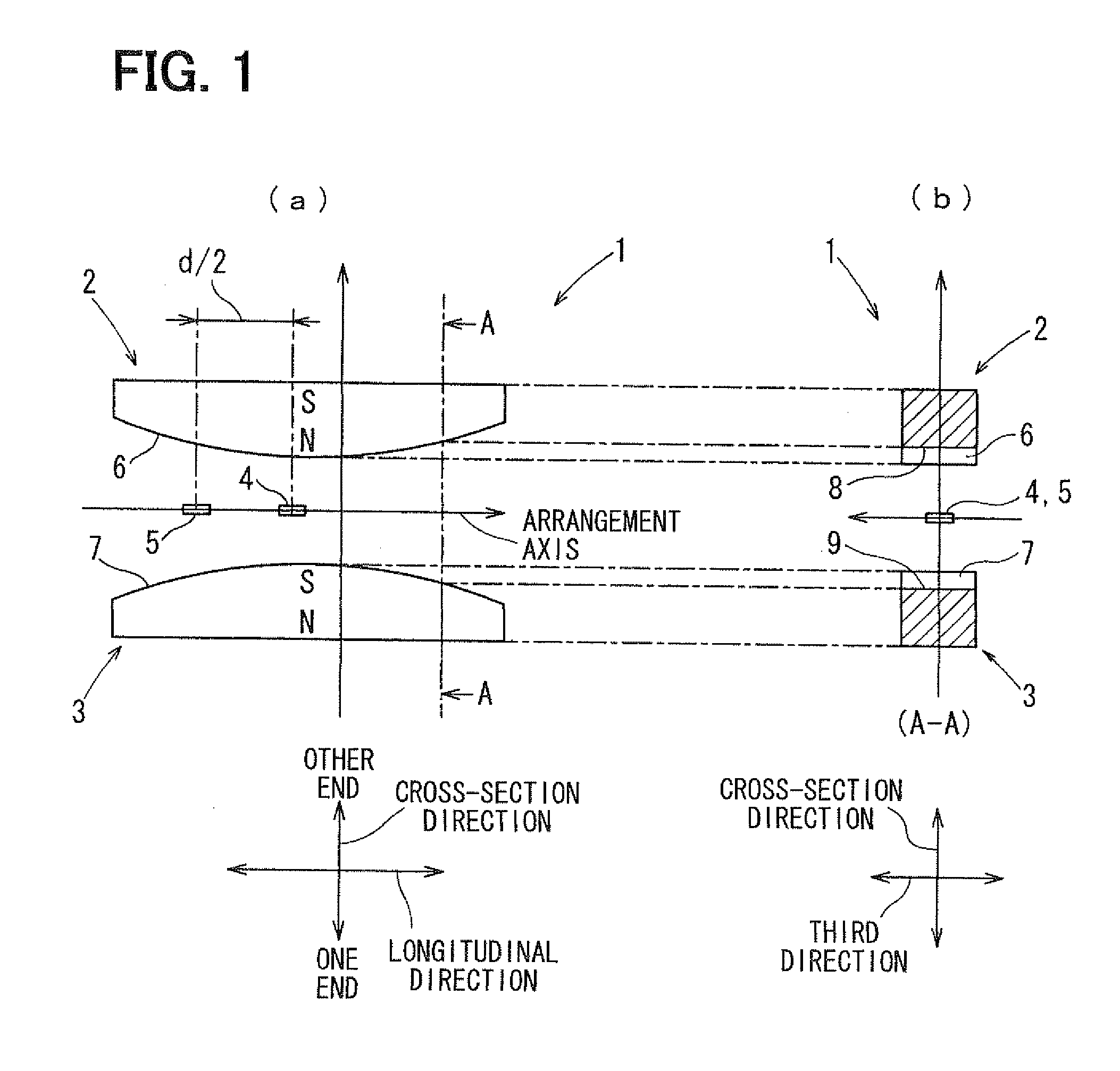
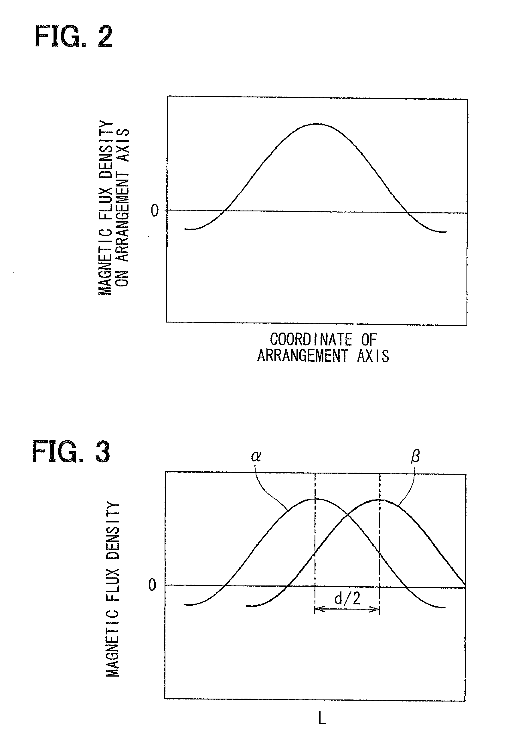
[0116]A construction of a stroke sensor 1 according to a first embodiment of the present invention will be explained with reference to FIGS. 1 to 6. The stroke sensor 1 senses a linear displacement amount (stroke amount) of a sensed body (not shown) displaced linearly. As shown in FIG. 1, the stroke sensor 1 has two magnets 2, 3 as movable members, which form a magnetic flux and are displaced linearly in accordance with the displacement of the sensed body, and two magnetism sensitive sections 4, 5 as fixed members, which sense the magnetic flux and convert the magnetic flux into electric outputs for outputting the electric outputs. The stroke sensor 1 is a non-contact sensor capable of sensing the stroke amount of the sensed body without causing contact between the movable member and the fixed member.

[0117]For example, the stroke sensor 1 is mounted in a vehicle and calculates an output value based on the electric outputs outputted from the two magnetism sensitive sections 4, 5. The...

second embodiment

[0153]Next, a stroke sensor 1 according to a second embodiment of the present invention will be explained. The stroke sensor 1 according to the second embodiment has magnetism sensitive sections 4, 5, which are compatible Hall elements having the identical performance and the identical characteristics. As shown in FIGS. 9A and 9B, the magnetism sensitive sections 4, 5 are provided by a single chip 20 together with a DSP 14 having functions of a first offset adjusting device 17, a first inverse trigonometric function calculating device 18 and a gain adjusting device 19.

[0154]The chip 20 further has functions of operational amplifiers 21, 22 amplifying output signals from the Hall elements as the magnetism sensitive sections 4, 5, an A / D converter 23 performing digital processing of the amplified output signals, and a D / A converter 15. Thus, the physique of the stroke sensor 1 can be reduced and the performance and the characteristics of the magnetism sensitive sections 4, 5 can be eq...

third embodiment

[0155]Next, a stroke sensor 1 according to a third embodiment of the present invention will be explained. As shown in FIG. 10, the stroke sensor 1 according to the third embodiment has a magnetic body 28 that covers peripheries 26, 27 of the magnets 2, 3 on sides opposite from the swelling end edges 6, 7 with respect to the magnetization direction. Thus, robustness against a disturbance magnetic field can be improved.


PUM


Abstract

A stroke sensor has two magnets, which are magnetized in a cross-section direction and are displaced in a longitudinal direction, and two magnetism sensitive sections arranged parallel to the longitudinal direction. The magnets have circular-arc-shaped swelling end edges respectively and are magnetized such that the swelling end edges have opposite polarities. Thus, a distribution of a magnetic flux density on an arrangement axis substantially coincides with a sine curve. The magnetic flux having such the distribution is displaced in the longitudinal direction together with the magnets. The magnetism sensitive sections are arranged on the arrangement axis to be distant from each other by a distance of one fourth of a cycle of the sine curve. Thus, the stroke sensor that is not affected by temperature and that has high sensing accuracy can be provided.

Description

CROSS REFERENCE TO RELATED APPLICATION[0001]This application is based on and incorporates herein by reference Japanese Patent Applications No. 2009-17870 filed on Jan. 29, 2009 and No. 2009-195255 filed on Aug. 26, 2009.BACKGROUND OF THE INVENTION[0002]1. Field of the Invention[0003]The present invention relates to a stroke sensor that senses a linear displacement amount (i.e., stroke amount) of a sensed body, which is displaced linearly, and to a rotation angle sensor that senses a rotation angle of a sensed body, which rotates.[0004]2. Description of Related Art[0005]Conventionally, many output values of stroke sensors and rotation angle sensors are used for various types of control of a vehicle and occupy important places in the control. For example, the stroke sensor has a movable member, which forms a magnetic flux and which is displaced linearly in accordance with linear displacement of a sensed body, and a fixed member, which senses the magnetic flux and converts the magnetic...

Claims


Application Information

Patent Timeline
IPC IPC(8): G01B7/30
CPCG01D5/145F02D41/009G01D2205/22G01D2205/26
Inventor MATSUMOTO, KOICHIROAOKI, TETSUYAKAWASHIMA, TAKASHIKITANAKA, TATSUYAKONO, YOSHIYUKI
Owner DENSO CORP
Why Eureka
Try Eureka