
Display apparatus and information input apparatus

a technology of information input and display apparatus, which is applied in the field of display apparatus and information input apparatus, can solve the problems of affecting the operation of the apparatus, and affecting so as to increase the image quality and the reliability of the apparatus

Inactive Publication Date: 2010-07-29
JAPAN DISPLAY WEST
View PDF10 Cites 66 Cited by
  • Summary
  • Abstract
  • Description
  • Claims
  • Application Information

AI Technical Summary

Benefits of technology

[0018]To overcome the above-mentioned problem, it can be thought that an area of the surface of the convex portion, on which the touch electrode is provided, is increased. In this case, however, an aperture ratio of the liquid crystal panel is reduced, which may result in the reduction in quality of the display image.
[0020]In view of the above-mentioned circumstances, it is desirable to provide a display apparatus and an information input apparatus that are capable of increasing the image quality and increasing the reliability of the apparatuses.
[0024]According to the present invention, it is possible to provide the display apparatus and the information input apparatus that are capable of increasing the image quality and the reliability of the apparatuses.

Problems solved by technology

However, in the display apparatus mentioned above, along with the reduction in thickness of the display panel, a member such as the electrode may be damaged by the external pressure, which may impair reliability of the apparatus.
In particular, in the case where the touch electrodes each are provided on the convex portion in the liquid crystal panel having the built-in touch sensor switch, the above problem may be apparently exposed because the touch electrode has a rigid body.
For example, the touch electrodes are disconnected, and the touch panel function may be impaired.
In addition, conductive foreign matters generated by crushing the touch electrodes may disperse in the liquid crystal cell, with the result that a problem of short-circuiting the touch electrodes may be caused.

Method used


Image

  • Display apparatus and information input apparatus
  • Display apparatus and information input apparatus
  • Display apparatus and information input apparatus

Examples


first embodiment

1. First Embodiment

Structure of Liquid Crystal Display Apparatus

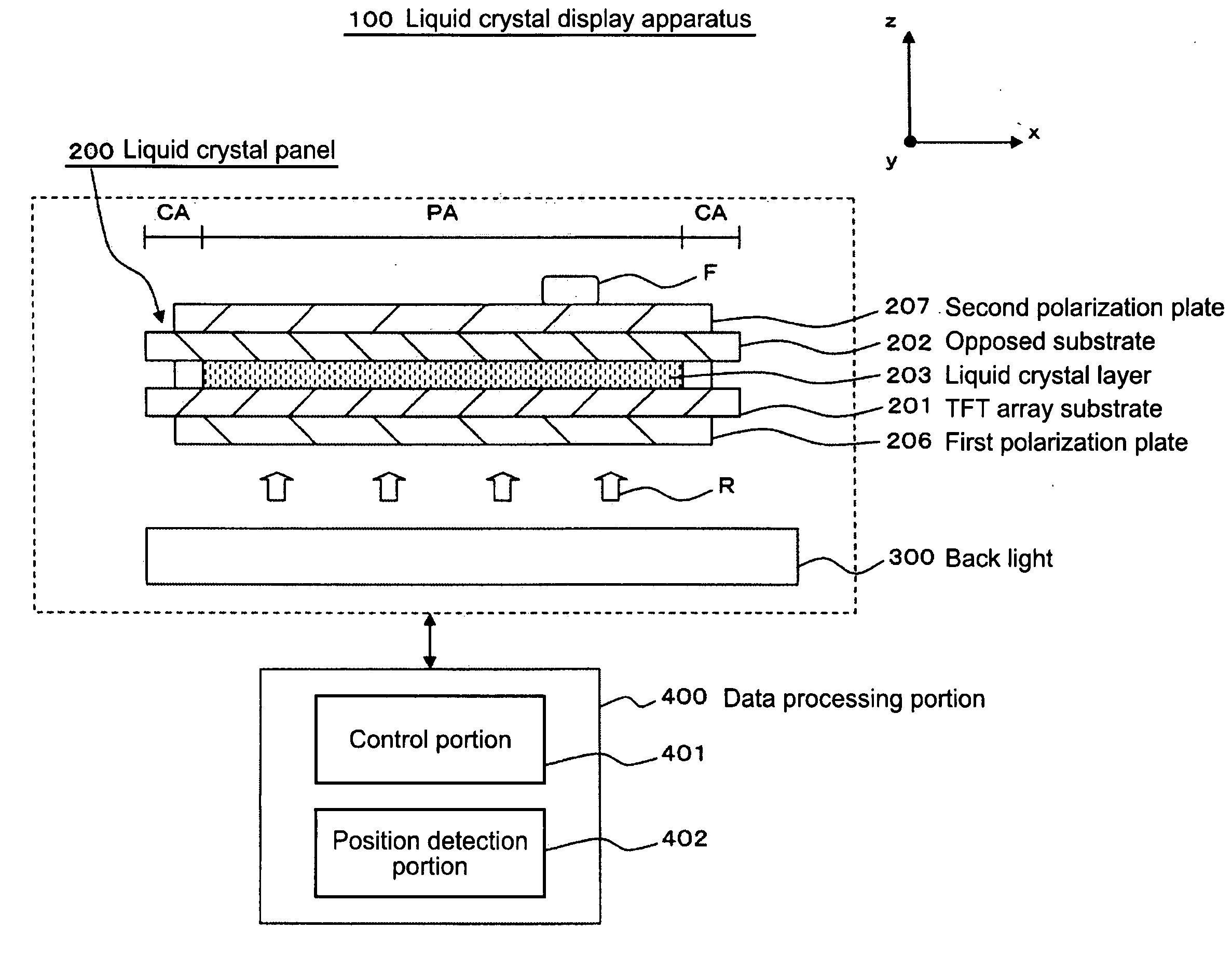
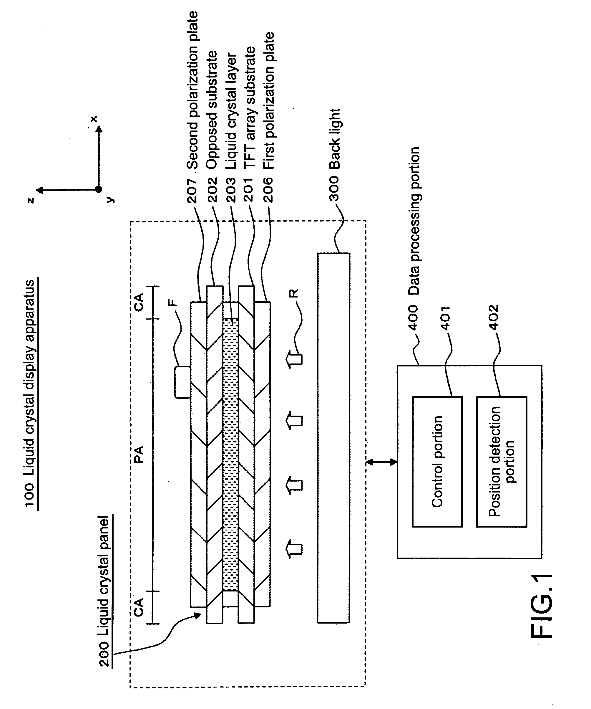
[0049]FIG. 1 is a cross-sectional view showing a structure of a liquid crystal display apparatus 100 according to a first embodiment of the present invention.

[0050]As shown in FIG. 1, the liquid crystal display apparatus 100 of this embodiment includes a liquid crystal panel 200, a backlight 300, and a data processing portion 400. Those portions will be sequentially described.

[0051]The liquid crystal panel 200 is an active matrix type, for example, and includes a TFT array substrate 201, an opposed substrate 202, and a liquid crystal layer 203, as shown in FIG. 1. In the liquid crystal panel 200, the TFT array substrate 201 and the opposed substrate 202 are opposed to each other at an interval. Further, the liquid crystal layer 203 is provided between the TFT array substrate 201 and the opposed substrate 202.

[0052]As shown in FIG. 1, in the liquid crystal panel 200, on a surface of the TFT array substrate 201 that const...

second embodiment (

2. Second Embodiment (Case where FFS Mode is Employed)

[0141]Hereinafter, a second embodiment of the present invention will be described.

(Detailed Structure of Liquid Crystal Panel)

[0142]A detailed structure of a liquid crystal panel 200b of this embodiment will be described.

[0143]FIGS. 9 and 10 are diagrams each showing main components of the liquid crystal panel 200b according to the second embodiment of the present invention.

[0144]Here, FIG. 9 is a cross-sectional view schematically showing an outline of the pixel P provided on the display area PA in the liquid crystal panel 200b according to the second embodiment of the present invention.

[0145]Further, FIG. 10 is a top view schematically showing the outline of the pixel P provided on the display area PA in the liquid crystal panel 200b in the second embodiment of the present invention. It should be noted that FIG. 9 shows the cross-sectional view taken along the line X1b-X2b of FIG. 10, but the display of the components is simpli...

third embodiment (

3. Third Embodiment (Case where Suspended Column is Provided)

[0158]Hereinafter, a third embodiment of the present invention will be described.

(Detailed Structure of Liquid Crystal Panel)

[0159]A detailed description will be given on a liquid crystal panel 200c of this embodiment.

[0160]FIG. 11 shows main components of the liquid crystal panel 200c according to the third embodiment of the present invention. FIG. 11 is a cross-sectional view schematically showing an outline of the liquid crystal panel 200c according to the third embodiment of the present invention.

[0161]As shown in FIG. 11, to the liquid crystal panel 200c of this embodiment, a suspended column UB is provided. The third embodiment is different from the first embodiment in this point and a point related thereto. A description on the same points as the first embodiment will be omitted.

[0162]As shown in FIG. 11, the suspended column UB is provided on the opposed substrate 202. The suspended column UB is formed on the side ...


PUM


Abstract

A display apparatus includes a display panel including a first substrate, a second substrate opposed to the first substrate, and a touch sensor switch disposed in a display area that displays an image. The touch sensor switch includes a first touch electrode provided on a surface of the first substrate and a second touch electrode provided on a surface of the second substrate. The touch sensor switch has a structure in which the first and second touch electrodes are brought into contact when the display panel is deformed by an external pressure. The first substrate includes a convex portion that protrudes in a convex shape toward the second substrate. The convex portion has a top surface opposed to the second substrate and includes a flat area formed on the top surface. The first touch electrode is formed in the flat area on the convex portion as an isolated pattern.

Description

BACKGROUND OF THE INVENTION[0001]1. Field of the Invention[0002]The present invention relates to a display apparatus and an information input apparatus. In particular, the present invention relates to a display apparatus and an information input apparatus in which a touch sensor switch is provided on a pair of substrates opposed to each other.[0003]2. Description of the Related Art[0004]A display apparatus such as a liquid crystal display apparatus and an organic EL display apparatus has advantages of being thin, lightweight, and small in power consumption. Therefore, a display apparatus is widely being used for a mobile electronic apparatus such as a cellular phone and a digital camera.[0005]Among such display apparatuses, a liquid crystal display apparatus has, as a display panel, a liquid crystal panel in which a liquid crystal layer is sealed between a pair of substrates. The liquid crystal panel is a transmissive type, and modulates and transmits illumination light emitted from...

Claims


Application Information

Patent Timeline
IPC IPC(8): G06F3/045
CPCG02F1/13338G06F3/0412G06F3/045G09G3/3648G09G2300/0426G02F2203/09G09G2310/0251G09G2310/0262G02F1/134363G02F1/136286G09G2300/0439
Inventor TAMAKI, MASAYAKOITO, TAKEO
Owner JAPAN DISPLAY WEST
Features
  • Generate Ideas
  • Intellectual Property
  • Life Sciences
  • Materials
  • Tech Scout
  • Unparalleled Data Quality
  • Higher Quality Content
  • 60% Fewer Hallucinations
Learn More