Display device

a display screen and display technology, applied in the field of display devices, can solve the problems of streaky luminance unevenness on the display screen, and achieve the effects of wide color reproducibility, secure writing time to a tft, and high quality

Inactive Publication Date: 2010-07-29
SHARP KK
View PDF11 Cites 73 Cited by
  • Summary
  • Abstract
  • Description
  • Claims
  • Application Information

AI Technical Summary

Benefits of technology

[0017]According to various preferred embodiments of the present invention, a display device is provided that has wide color reproducibility due to multi-primary color image display, and that secur

Problems solved by technology

However, the occurrence of streaky luminance unevenness on the display screen has been confirmed, in the case where inversion driving such as dot inversion driving or lin

Method used


Image

  • Display device
  • Display device
  • Display device

Examples


first preferred embodiment

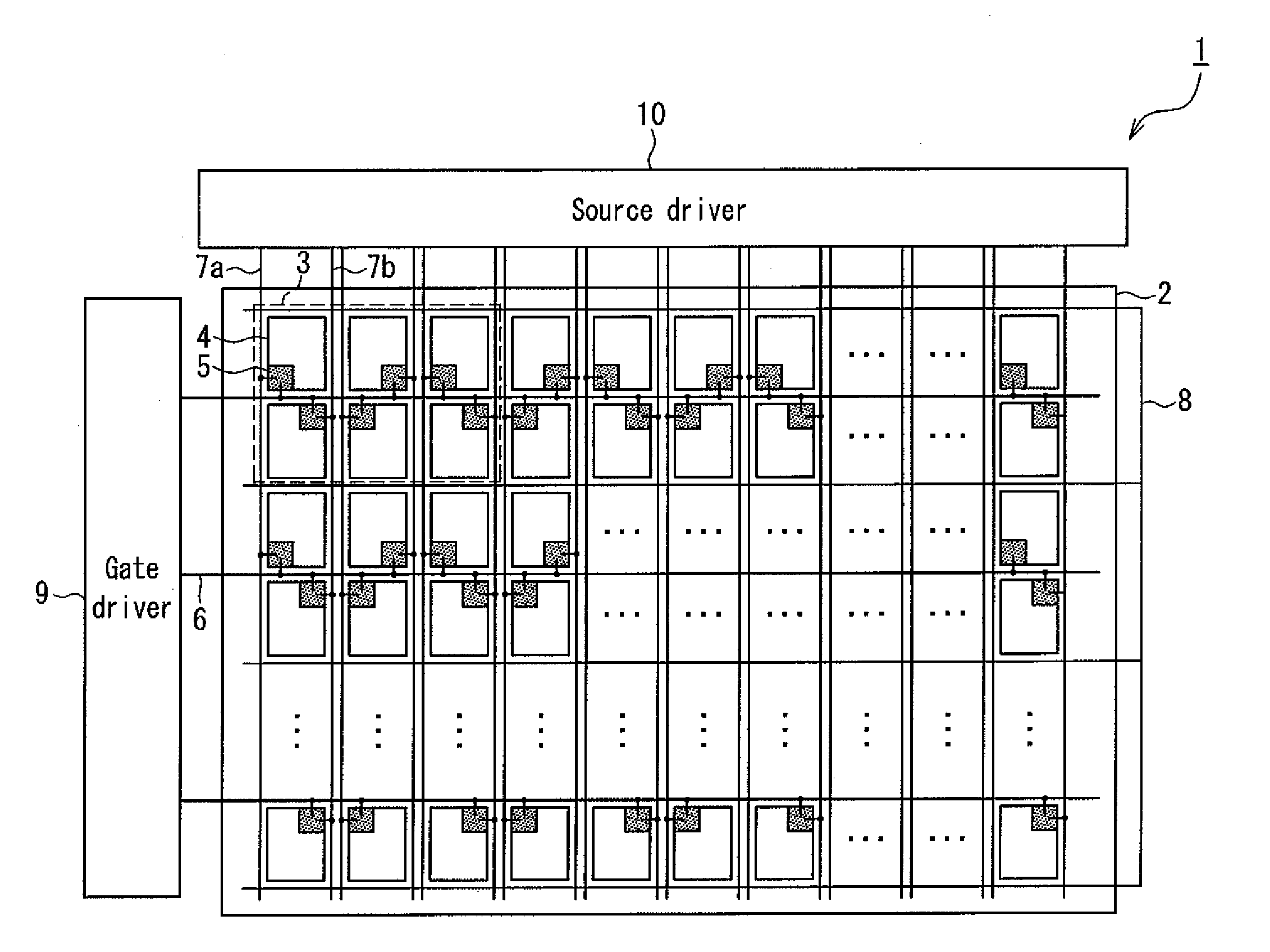
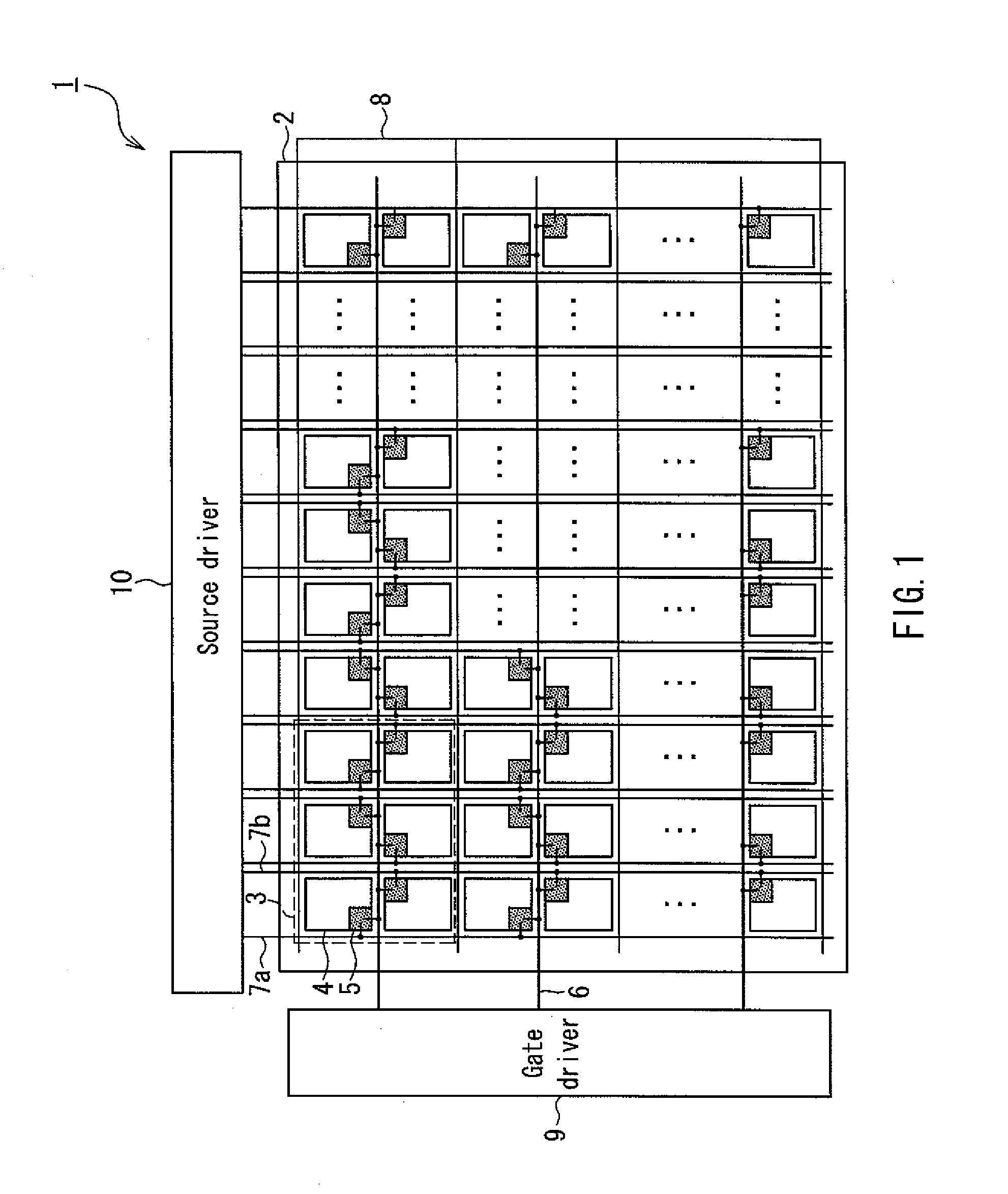
[0052]FIG. 1 is a block configuration diagram illustrating a display device according to a first preferred embodiment of the present invention. As shown in FIG. 1, a display device 1 of the present preferred embodiment is provided with a transmissive liquid crystal panel 2, which a display element, a gate driver 9, and a source driver 10.

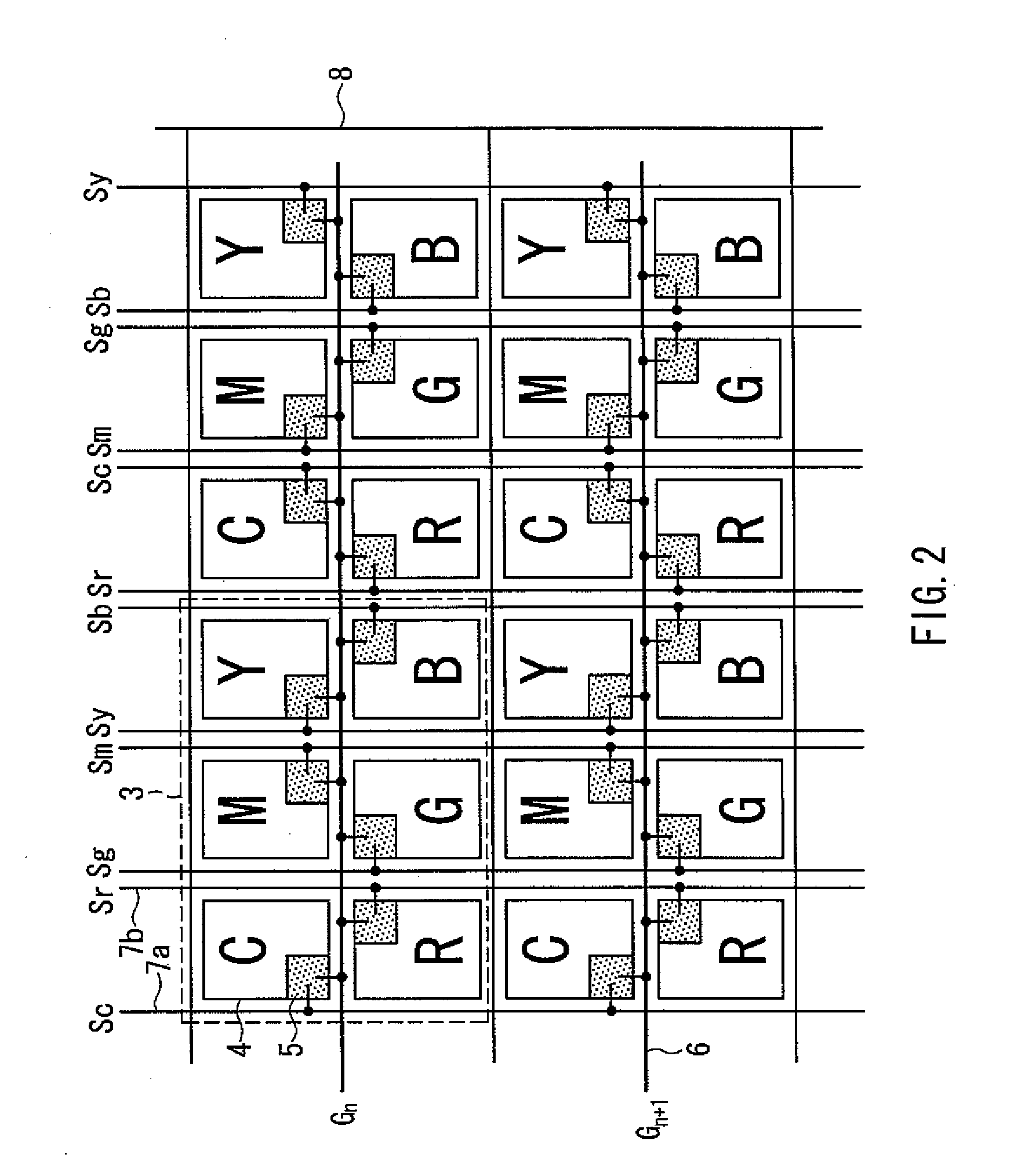
[0053]In the liquid crystal panel 2, a total of six picture elements 4 disposed in two lines in the longitudinal direction and three columns in the lateral direction constitute a single pixel 3, for example. While the colors of the picture elements 4 are decided by color filters formed in respective picture element areas, illustration thereof is omitted in FIG. 1. Note that the array of these color filters, that is, the array of colors of the picture elements 4 will be discussed later referring to FIG. 2 and beyond.

[0054]Each picture element 4 is provided with a TFT 5, which is a switching element arranged to control light transmissivity in the pict...

second preferred embodiment

[0128]Hereinafter, various patterns of picture element arrays in a liquid crystal display panel according to the present invention will be described as a second preferred embodiment. Note that because the configuration serving as a display device 1 that includes the configuration of a liquid crystal panel 2, and driving circuits such as a gate driver 9 and a source driver 10 for performing image display by driving the liquid crystal panel 2, shown as the following second preferred embodiment, other than the patterns of picture element arrays, is preferably substantially the same as that according to the first preferred embodiment described above, description thereof will be omitted.

[0129]Also, illustrated as the picture element array patterns serving as the second preferred embodiment in FIGS. 10A and 10B and beyond is the case where, as a result of a picture element constituting an adjoining pixel being inversion driven, the effective value relative to the image display signal of a...


PUM


Abstract

A display device prevents luminance unevenness that occurs in the case of inversion driving being performed, and performs high quality image display, while selectively scanning two lines of picture elements constituting a single pixel using a single gate wiring, as in the case of multi-primary color image display. The display device includes a display element including a pixel constituted by a plurality of picture elements disposed in two lines in a longitudinal direction and two or more columns in a lateral direction, a gate wiring common to the plurality of picture elements, and a source wiring that is arranged perpendicular or substantially perpendicular to the gate wiring and to perform image display using inversion driving in which an image display signal is provided to the picture elements connected to the gate wiring which is sequentially selected, at a different polarity than a polarity of an immediately previous frame, and an array of the picture elements in the pixel is determined so as to compensate for a change in luminance following the change in the effective value relative to the image display signal of the picture elements belonging to one line.

Description

BACKGROUND OF THE INVENTION[0001]1. Field of the Invention[0002]The present invention relates to a display device in which pixels are constituted by two lines of picture elements connected to a single gate wiring, and more particularly, to a display device that makes luminance unevenness less likely to occur by the array of picture elements, even when inversion driving is performed.[0003]2. Description of the Related Art[0004]In recent years, flat display devices such as liquid crystal display devices and EL display devices characterized by having low power consumption and being slim and lightweight have been widely used as display devices such as television receivers. With flat panels such as liquid crystal panels and EL panels used in flat display devices, image display is normally performed with a driving method called an active matrix method. This active matrix method involves displaying an image by selecting and driving TFTs, which are switching elements formed in each of a plu...

Claims


Application Information

Patent Timeline
IPC IPC(8): G09G3/36G09G5/10
CPCG02F1/13624G02F1/136286G09G3/3614G02F2201/52G02F2001/134345G02F1/134345
Inventor ITOH, RYOHKIHORIUCHI, SATOSHIHISADA, YUHKO
Owner SHARP KK
Why Eureka
Try Eureka