Building method and building apparatus

a building method and building technology, applied in the direction of additive manufacturing processes, manufacturing tools, manufacturing data acquisition/processing, etc., can solve the problems of different surface colors of objects, thinned color regions of objects,

Active Publication Date: 2019-04-04
MIMAKI ENG
View PDF0 Cites 1 Cited by
  • Summary
  • Abstract
  • Description
  • Claims
  • Application Information

AI Technical Summary

Benefits of technology

[0010]With this configuration, color quality of the object surface can be controlled. For example, when the surface color region is thinned, a clear color can be reproduced with high-resolution. Alternatively, when the surface color region is thickened, stable and wide color reproducibility having small variation in lots can be achieved. In a case of having a clear region on the outside of the surface color region (that is, an outermost surface of the object), the surface color region encompasses the clear region.
[0030]In this way, by constituting the machining allowance with clear ink, even when the machining allowance remains in polishing the object thereafter, the machining allowance is transparent and inconspicuous.

Problems solved by technology

There has been a problem such that, when the surface of the color object is polished, the color region of the object surface is thinned, and a surface color of the object is different from intended coloring.

Method used


Image

  • Building method and building apparatus
  • Building method and building apparatus
  • Building method and building apparatus

Examples


first embodiment

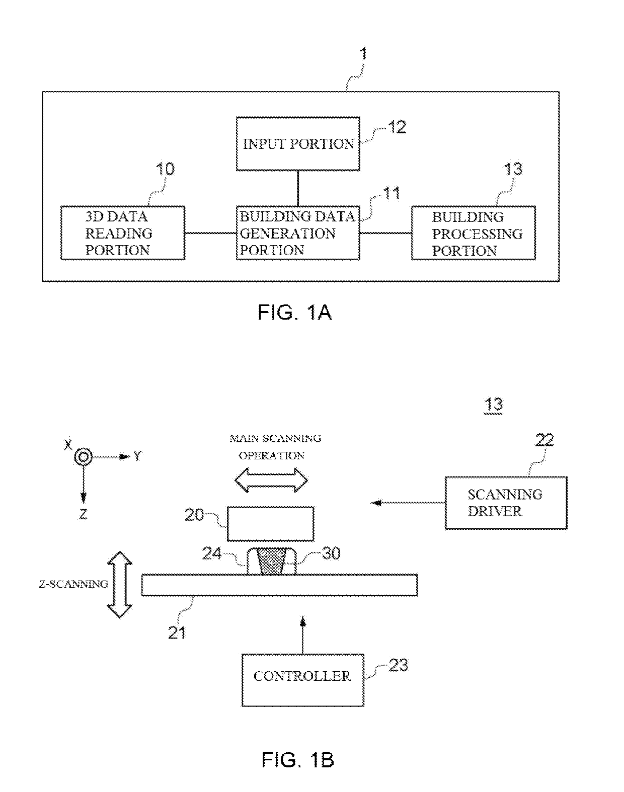
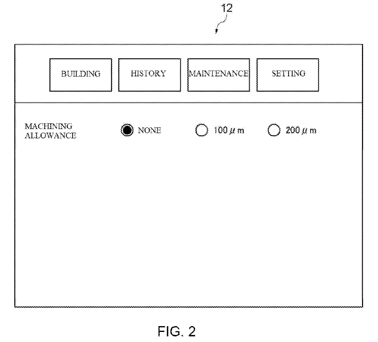
[0041]FIGS. 1A and 1B are diagrams illustrating a configuration of a building apparatus 1 according to a first embodiment. As illustrated in FIG. 1A, the building apparatus 1 includes a 3D data reading portion 10 that reads 3D data on an object, a building data generation portion 11 that generates building data from the 3D data, an input portion 12 that receives an input of various settings and the like from a user, and a building processing portion 13 that deposits UV ink based on the building data to generate the object.

[0042]The 3D data is data on a shape and a surface color of the object and is created based on data on external appearance and the like obtained by photographing the object to be manufactured. The 3D data is, for example, handled as a file in a format such as “VRML”, “OBJ”, and “PLY.” The building data generation portion 11 has a function of generating data that defines a material, a color, and the like constituting the object based on the 3D data, and defines whic...

second embodiment

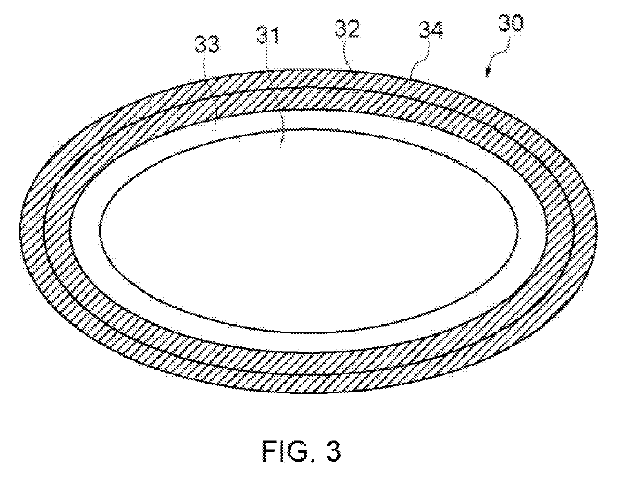
[0057]Next, the following describes the building apparatus according to a second embodiment. A basic configuration and operation of the building apparatus according to the second embodiment are the same as those in the first embodiment. In the second embodiment, at the time when the building data generation portion 11 adds the machining allowance to the object 30, color density of the surface color region 32 of the object 30 is changed in accordance with the thickness of the machining allowance.

[0058]FIG. 6 is a diagram illustrating an example of the building data including the machining allowance 34. In the second embodiment, the color density is lowered corresponding to the thickness of the machining allowance 34, and the machining allowance 34 made of the building material having the same color density as the lowered color density is added. To lower the color density, density of the color ink is lowered, but design is made such that clear ink is filled in a portion where the colo...

third embodiment

[0061]Next, the following describes a building apparatus according to a third embodiment. A basic configuration and operation of the building apparatus according to the third embodiment are the same as those in the first embodiment. In the third embodiment, clear ink is used for the machining allowance to be added to the surface of the object 30.

[0062]FIG. 7 is a diagram illustrating the building data on the object 30 generated by the building apparatus according to the third embodiment. As illustrated in FIG. 7, the machining allowance 34 made of the clear ink is added to the object 30.

Effect of Embodiments

[0063](1) The building method according to the present embodiment includes Step S12 for receiving the data on the thickness of the machining allowance of the object 30 from the user, Step S14 for generating the building data including the machining allowance 34 having the set thickness, and Step S16 for generating the object 30 by depositing the building material based on the bui...


PUM

PropertyMeasurementUnit
thicknessaaaaaaaaaa
surface coloraaaaaaaaaa
color densityaaaaaaaaaa

Abstract

To provide a building method and a building apparatus for building an object having an inconspicuous deposition streak. The building method includes: receiving, from a user, a data on a thickness of a machining allowance added to the object; generating a building data to which a machining allowance having an input thickness is added; generating the object by depositing a building material based on the building data; and polishing a surface of the object.

Description

CROSS REFERENCE TO RELATED APPLICATIONS[0001]This application claims the priority benefit of Japanese Patent Application No. 2017-190877, filed on Sep. 29, 2017. The entirety of the above-mentioned patent application is hereby incorporated by reference herein and made a part of this specification.TECHNICAL FIELD[0002]The present disclosure relates to a building method and a building apparatus.BACKGROUND ART[0003]In the related art, there is known a building apparatus (3D printer) that builds an object using an ink-jet head. In such a building apparatus, for example, the object is built by stacking a plurality of layers of ink formed by the ink-jet head.[0004]In a case of building the object using the ink-jet head, an object colored in various colors can be built by using ink for coloring as a building material. The object can be variously decorated by drawing a design such as various characters and patterns on a surface of the object (Patent Literature 1).[0005]Patent Literature 1: ...

Claims


Application Information

Patent Timeline
Patent Type & Authority Applications(United States)
IPC IPC(8): B29C64/393B29C64/112B33Y10/00B33Y30/00B33Y50/02
CPCB29C64/393B29C64/112B33Y10/00B33Y30/00B33Y50/02B29C64/40B29C64/10
Inventor TANAKA, YOSHIHIROOHI, HIROYOSHI
Owner MIMAKI ENG
Why Eureka
Try Eureka