Printing head for NANO patterning

a printing head and nano-patterned technology, applied in the field of nano-patterned printing heads, can solve the problems of reducing accuracy, time-consuming, and limiting the use of materials, and achieve the effect of improving patterning accuracy

Inactive Publication Date: 2010-07-29
KOREA INST OF MACHINERY & MATERIALS
View PDF5 Cites 2 Cited by
  • Summary
  • Abstract
  • Description
  • Claims
  • Application Information

AI Technical Summary

Benefits of technology

[0011]Therefore, an object of the present invention is to provide a printing head for nano patterning, wherein patterning accuracy can be improved and ultra-fine patterning and the patterning of arbitrary shapes can be achieved.

Problems solved by technology

However, patterning methods using lithography and etching have problems in that a great deal of time is required for processes, contamination occurs due to foreign materials introduced during a patterning process, there is a limitation on employing materials, and accuracy is lowered due to complicated processes.
Further, there is a problem in that it is difficult to perform ultra-fine patterning and the patterning of arbitrary shapes since areas to be patterned with the printing material are limited to operating areas of the printing head.

Method used


Image

  • Printing head for NANO patterning
  • Printing head for NANO patterning
  • Printing head for NANO patterning

Examples


Embodiment Construction

[0022]Hereinafter, preferred embodiments of the present invention will be described in detail with reference to the accompanying drawings.

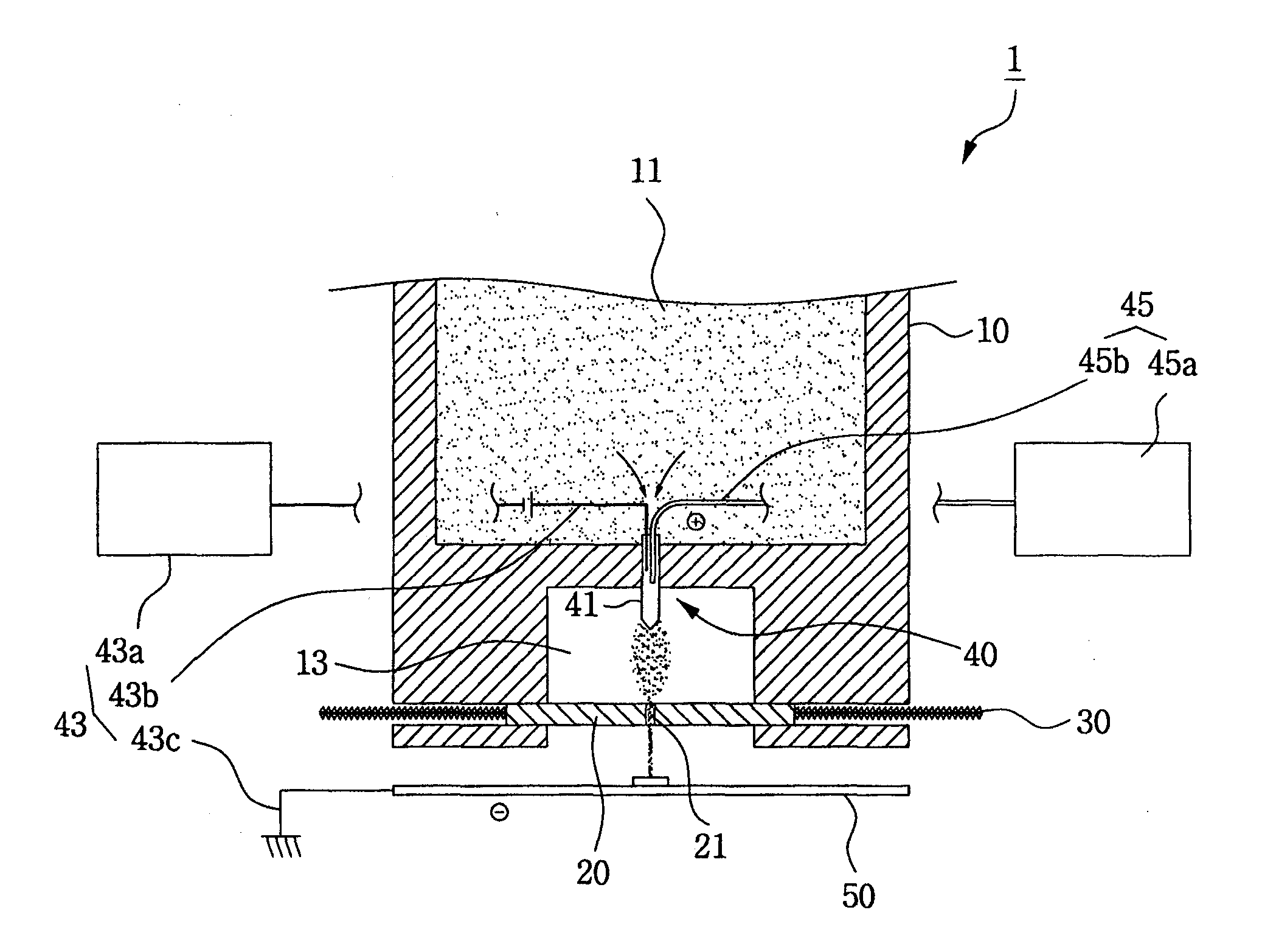
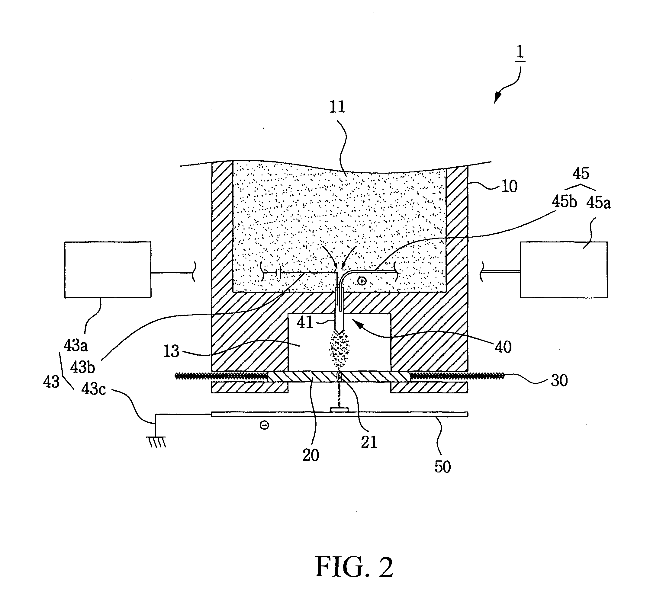
[0023]FIG. 2 is a sectional view schematically showing a printing head for patterning according to an embodiment of the present invention, and FIG. 3 is a perspective view showing a region of FIG. 2 where a shadow mask is installed. As shown in these figures, the printing head 1 for patterning according to the embodiment of the present invention comprises a cartridge 10 for accommodating a printing material, an injection-inducing unit 40 for inducing the injection of the printing material accommodated in the cartridge 10 to the outside, a shadow mask 20 that has a single injection hole 21 and is installed below the cartridge 10 to be finely moved so that areas on which the printing material will be injected can be controlled, an actuator 30 for finely moving the shadow mask 20, and a control unit (not shown) for controlling the driving of the prin...


PUM

PropertyMeasurementUnit
diameteraaaaaaaaaa
sizeaaaaaaaaaa
frequencyaaaaaaaaaa

Abstract

The present invention provides a printing head for nano patterning including a manifold for accommodating a liquid printing material, a cartridge with an injection chamber communicating with the manifold, and a sample holder for patterning installed outside the injection chamber of the cartridge. The printing head comprises a shadow mask which is installed outside the injection chamber to be finely moved in an X-Y direction and has a single injection hole with a relatively very small size; an actuator for finely moving the shadow mask; an injection-inducing unit including a high voltage generator, a power supply electrode that is installed within the injection chamber and receives power from the high voltage generator to generate positive charges, and an opposite electrode for generating negative charges on the sample holder in a state where the shadow mask is interposed between the power supply electrode and the opposite electrode, thereby generating induced discharge from the injection chamber toward the sample holder; and a control unit for controlling the driving of the actuator so that the injection hole of the shadow mask can be moved to patterning positions corresponding to patterning data input in advance. According to the present invention, patterning accuracy can be improved, ultra-fine patterning and patterning of arbitrary shapes can be achieved, and a configuration for injecting the printing material can be simplified.

Description

[0001]This application is a Divisional of application Ser. No. 11 / 417,114, filed May 4, 2006. This invention claims the benefit of Korean Patent Application No. 10-2003-078338 filed in Korea on Nov. 6, 2003 and International Patent Application No. PCT / KR2004 / 000687, filed on Mar. 26, 2004, which is hereby incorporated by reference in its entirety.TECHNICAL FIELD[0002]The present invention relates to a printing head for nano patterning, and more particularly, to a printing head for nano patterning, wherein the structure of a shadow mask and an injection configuration are improved so that patterning accuracy can be enhanced and ultra-fine nano patterning and the patterning of arbitrary shapes can be achieved.BACKGROUND ART[0003]As for typical examples of methods for patterning integrated circuits and microstructures in nano technologies such as semiconductor technology, there are lithography and etching.[0004]However, patterning methods using lithography and etching have problems in t...

Claims


Application Information

Patent Timeline
Patent Type & Authority Applications(United States)
IPC IPC(8): B41J29/38B41J2/07B01L3/02B41J2/14
CPCB01L3/0268B01L2400/027B82Y30/00B41J2/14B01L2400/0439B33Y30/00B41J2/07B82Y40/00C23C16/00
Inventor KIM, DONG-SOOLEE, WON-HEELEE, TAEK-MINCHOI, DOO-SUNCHOI, BYUNG-OH
Owner KOREA INST OF MACHINERY & MATERIALS
Why Eureka
Try Eureka