Method for improved vertical sweep of oil reservervoirs

a technology of oil reserve reservoirs and vertical sweeps, applied in the field of crude oil recovery, can solve the problems of severely limited recovery using the prior art, and achieve the effect of slowing down the segregation, increasing the recovery, and controlling the segregation

Inactive Publication Date: 2006-08-17
STONE HERBERT L
View PDF12 Cites 19 Cited by
  • Summary
  • Abstract
  • Description
  • Claims
  • Application Information

AI Technical Summary

Benefits of technology

[0010] In a WAG flood oil is displaced from a subterranean formation by injecting water alternately with gas through a single injection completion per pattern. The ratio of water to gas injected is the WAG ratio. Recovery using the prior art is severely limited by gravity segregation of the water and the second fluid. This invention increases recovery several-fold above that of the prior art, by using two distinct completion intervals per pattern and by using horizontal injection wells, to slow and control this segregation.

Problems solved by technology

Recovery using the prior art is severely limited by gravity segregation of the water and the second fluid.

Method used


Image

  • Method for improved vertical sweep of oil reservervoirs
  • Method for improved vertical sweep of oil reservervoirs
  • Method for improved vertical sweep of oil reservervoirs

Examples


Embodiment Construction

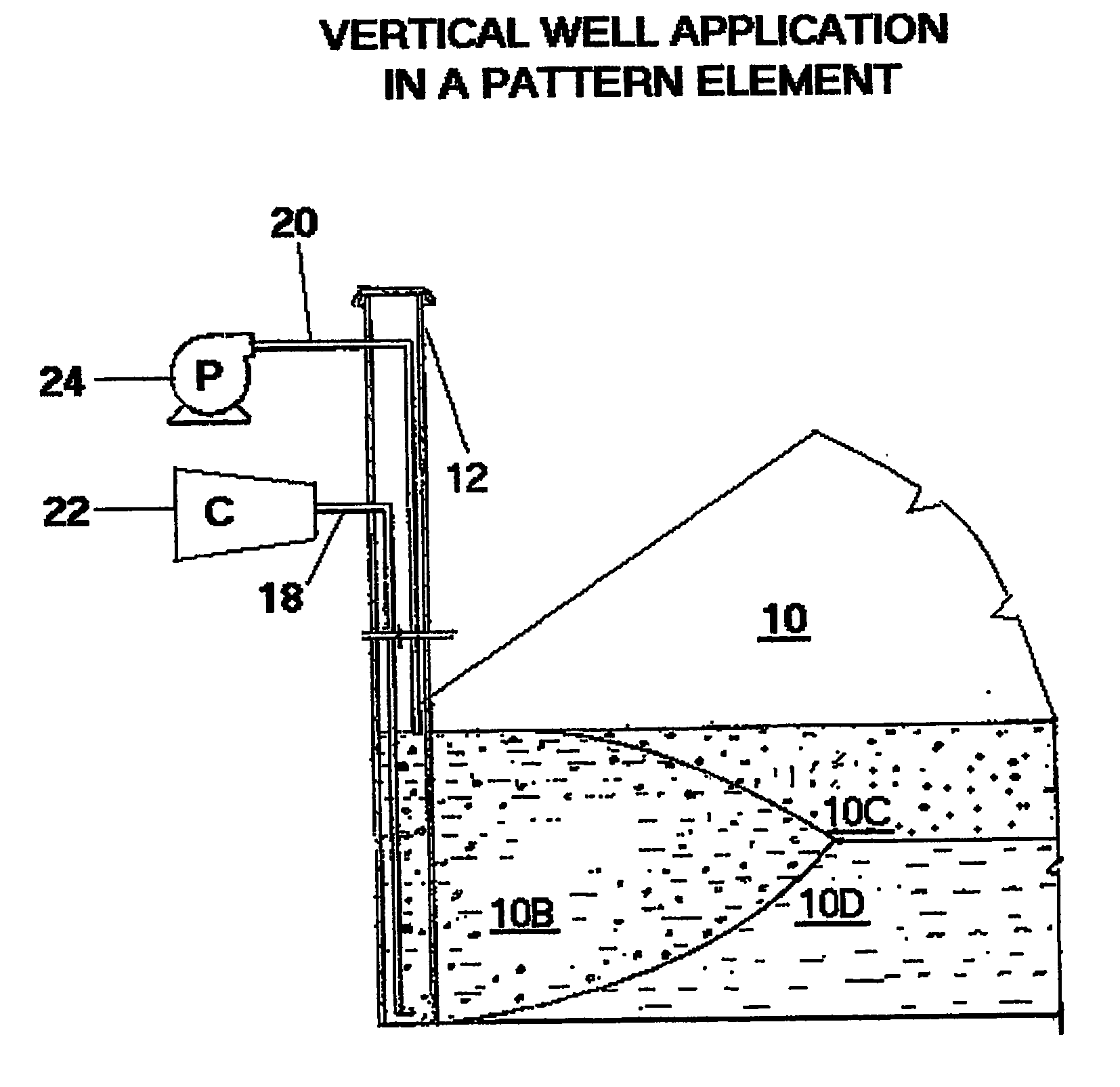
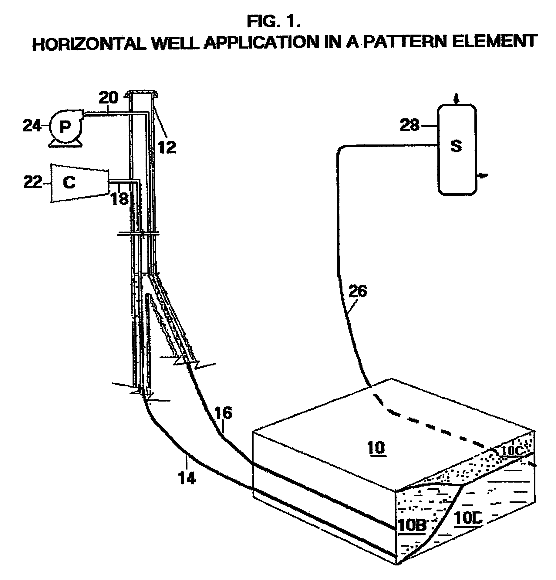
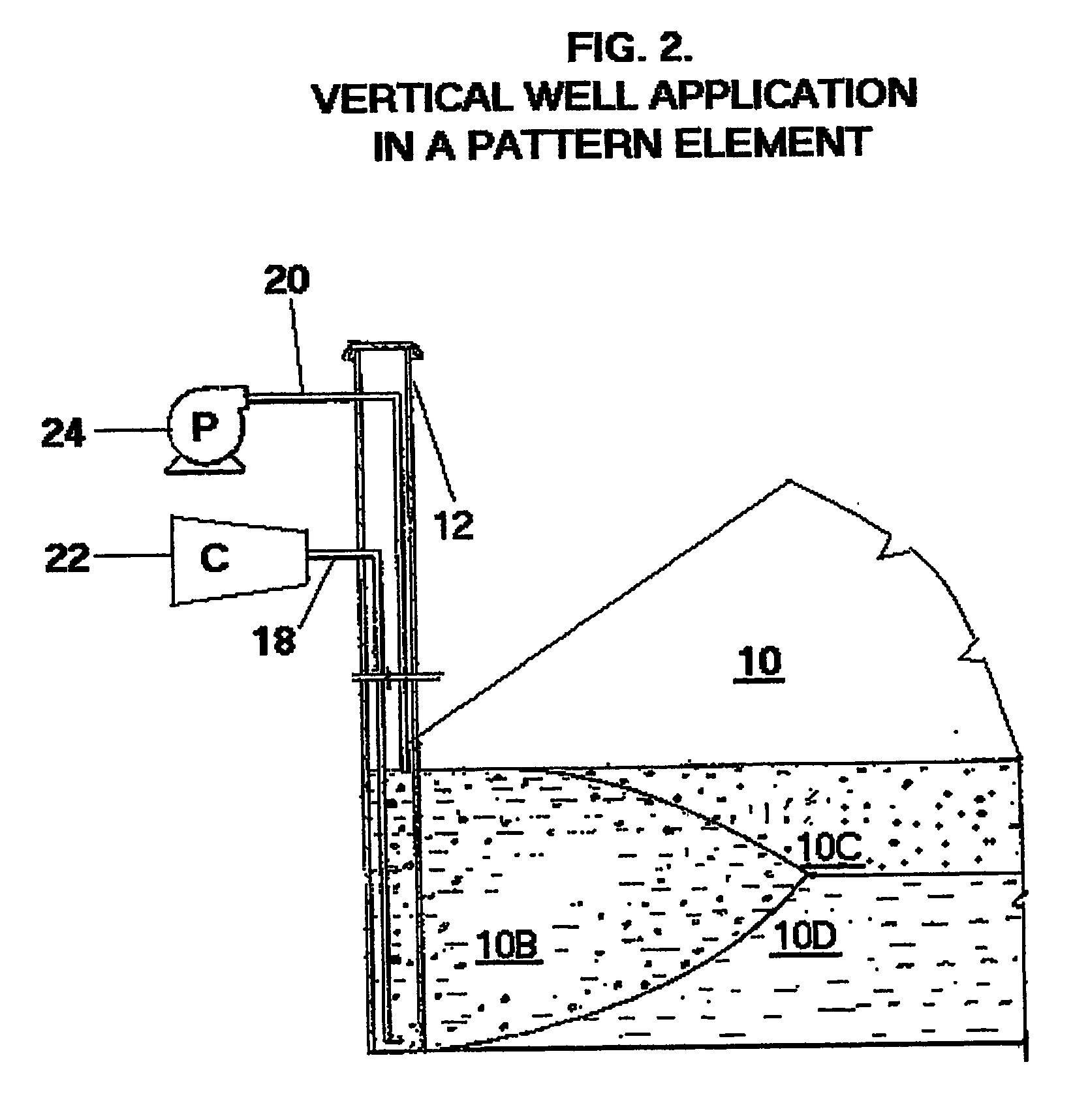
[0031] In a preferred embodiment, only second fluid is injected into the bottom injection interval, and only water into the top. At selected times and for selected time periods, the water injection is stopped. During these periods, gravity will cause the continuing second fluid injection to flow into the upper injection interval. When water injection is resumed, it will move this second fluid into the formation and mix with it. The net effect is a high WAG ratio injection into the upper part of the reservoir that can be controlled by the frequency and length of the interruptions of the water injection. The frequency of these water stoppages should be high, and the length short. The length should be no greater than the time it takes the second fluid injected at the bottom to reach the top of the reservoir. One way of accomplishing this shortness is to have a detector for the second fluid located near the top of the reservoir directly above the second fluid injector, perhaps placed in...


PUM


Abstract

In a WAG flood oil is displaced from a subterranean formation by injecting water alternately with gas into a single injection completion per pattern. The ratio of water to gas injected is the WAG ratio. In this invention, two separate injection completions are used in each pattern, with one placed directly above the other. A very low WAG ratio is used for injection into the bottom extremity of the formation. A very high WAG ratio is injected into the upper interval, at as high a rate can safely be used without fracturing the formation. In the preferred embodiment, two horizontal well bores serve as the two completion intervals. Proper design of this method gives a vertical sweep efficiency of the gas that is several-fold greater than the best of previous WAG flood designs, especially in thin formations.

Description

TECHNICAL FIELD [0001] This invention pertains to recovery of crude oil from subterranean reservoirs by injecting both water and a second less dense fluid to displace the oil, preferably through horizontal wells. The invention is based on the proper selection of spacing and relative location of injection and production wells, and proper selection of injection rates and location of injection completion intervals for both water and the second fluid. BACKGROUND ART [0002] Although gas efficiently displaces oil in a vertical downward displacement that is aided by gravity, gas displacement of oil by predominantly horizontal flow is inefficient because of the low viscosity of the gas relative to the oil. The gas fingers through the oil, giving poor conformance and resulting in a low recovery of the oil. Injecting water along with the gas was proposed to control this fingering and poor conformance. The water decreases the mobility of the gas by lowering the relative permeability of the for...

Claims


Application Information

Patent Timeline
Patent Type & Authority Applications(United States)
IPC IPC(8): E21B47/10E21B43/22E21B43/18E21B43/20E21BE21B43/00E21B43/16
CPCE21B43/166E21B43/162
Inventor STONE, HERBERTL
Owner STONE HERBERT L
Why Eureka
Try Eureka