Road lane marker detection apparatus and road lane marker detection method

a detection apparatus and lane marker technology, applied in the direction of television systems, instruments, roads, etc., can solve the problems of low contrast between the dots or the like and the asphalt, poor continuity in the length direction of the road, and the detection accuracy may decrease, so as to achieve the effect of reliably detecting the line lane marker

Active Publication Date: 2010-07-29
TOYOTA JIDOSHA KK
View PDF7 Cites 15 Cited by
  • Summary
  • Abstract
  • Description
  • Claims
  • Application Information

AI Technical Summary

Benefits of technology

[0014]The invention provides a road lane marker detection apparatus and a road lane marker detection method capable of more reliably detecting a line lane marker and a dotted lane marker ev

Problems solved by technology

Compared to a white line or the like, Botts' dots or the like have low contrast with asphalt and have poor continuity in the length direction of the road.
This is because the detection accuracy may decrease if an attempt is made to uniformly detect both a white line or the like and Botts' dots or the like using the same method of analysis.
The reason for this is that the continuity of Botts' dots or the like is poor so a sufficient number of feature p

Method used


Image

  • Road lane marker detection apparatus and road lane marker detection method
  • Road lane marker detection apparatus and road lane marker detection method
  • Road lane marker detection apparatus and road lane marker detection method

Examples


Embodiment Construction

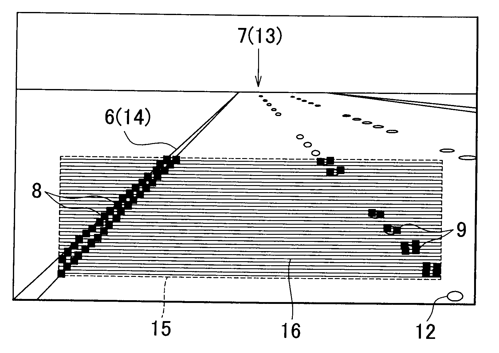
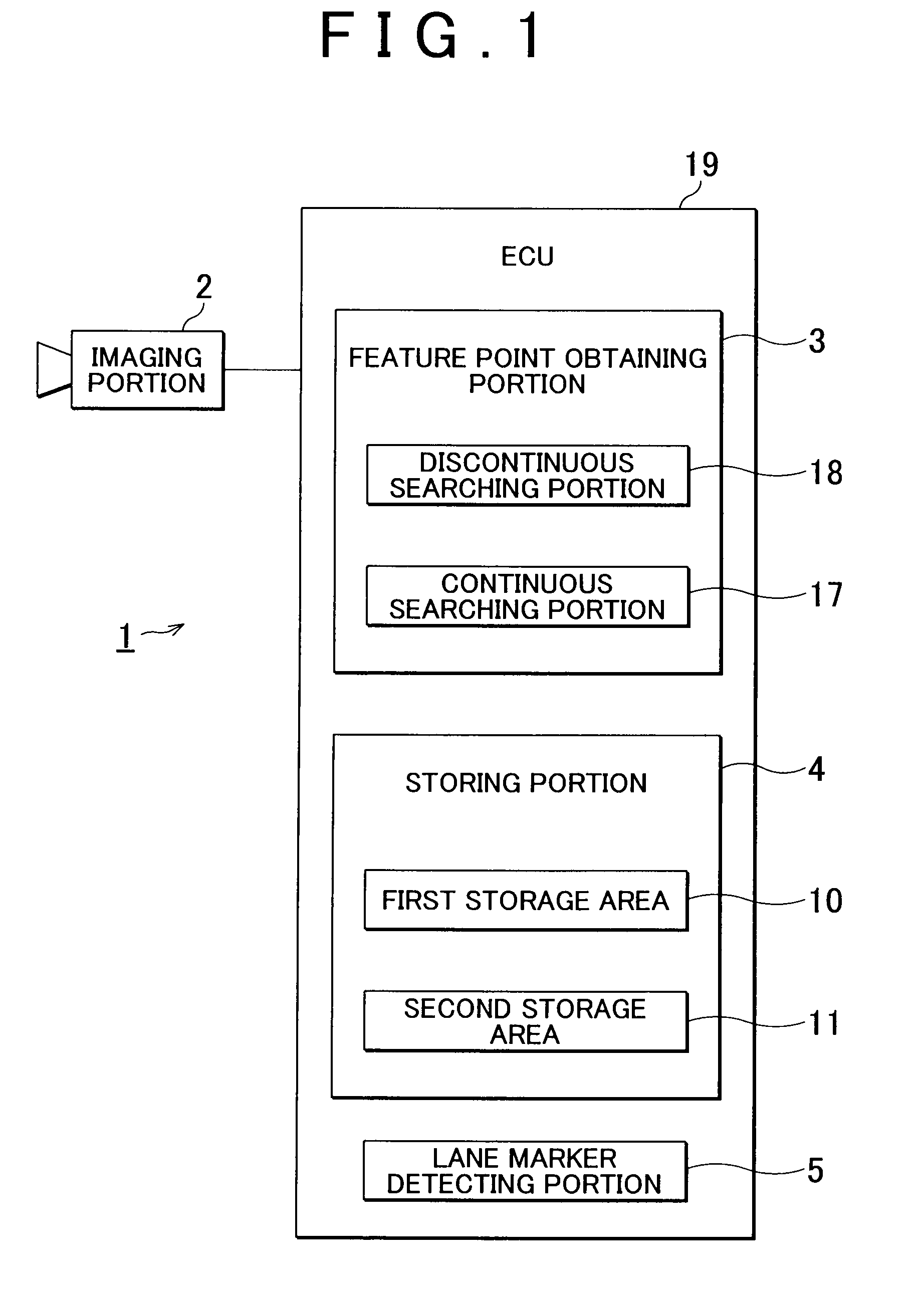
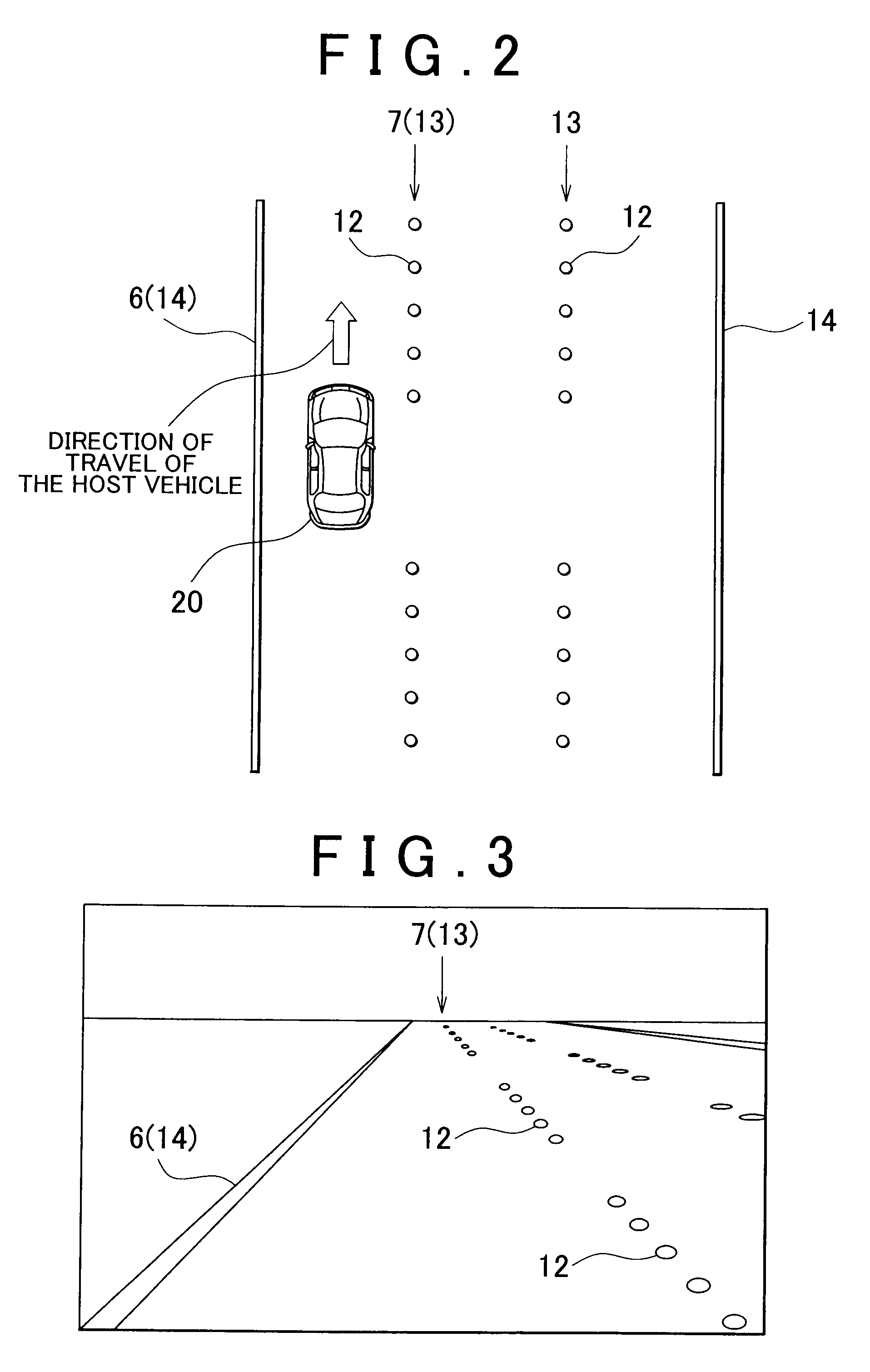
[0032]A road lane marker detection apparatus according to one example embodiment of the invention will now be described with reference to the accompanying drawings. FIG. 1 is a block diagram of a road lane marker detection apparatus according to the example embodiment. FIG. 2 is a plan view of a road with three lanes in one direction in which the road lane markers on the edges of the road (the road boundary markers) are line lane markers and the road lane markers at the lane boundaries (lane boundary markers) are dotted lane markers. FIG. 3 is a view of a captured image when the road shown in FIG. 2 is captured by a camera, and FIG. 4 is a view of a Botts' dot.

[0033]The road lane marker detection apparatus 1 according to this example embodiment is an apparatus that detects a road lane marker on a road. The road lane marker detection apparatus 1 is provided in a host vehicle 20 (see FIG. 2). In the example described below, the host vehicle 20 is traveling on a road with a plurality o...


PUM


Abstract

A road lane marker detection apparatus includes an imaging portion that captures an image of the road surface such that a first road lane marker and a second road lane marker are captured in the image; a feature point obtaining portion that obtains feature points of the road lane markers; a storing portion that stores the feature points obtained; and a lane marker detecting portion that detects the road lane markers. The storing portion includes a first storage area in which the feature points of the first road lane marker are stored and a second storage area in which the feature points of the second road lane marker are stored. The number of feature points able to be stored in the first storage area and the number of feature points able to be stored in the second storage area are set independently of one another.

Description

INCORPORATION BY REFERENCE[0001]The disclosure of Japanese Patent Application No. 2009-013172 filed on Jan. 23, 2009 including the specification, drawings and abstract is incorporated herein by reference in its entirety.BACKGROUND OF THE INVENTION[0002]1. Field of the Invention[0003]The invention relates to a road lane marker detection apparatus and a road lane marker detection method. More particularly, the invention relates to a road lane marker detection apparatus and road lane marker detection method capable of more reliably detecting a line lane marker and a dotted lane marker even if one of the road lane markers, from among a road lane marker on the left side of the vehicle and a road lane marker on the right side of the vehicle, is a line lane marker such as a white line and the other road lane marker is a dotted lane marker formed by Botts' dots or the like.[0004]2. Description of the Related Art[0005]In recent years, drive assist systems such as a lane keeping assist system...

Claims


Application Information

Patent Timeline
IPC IPC(8): H04N7/18B60R1/00G06T1/00G06T7/00G08G1/16
CPCG06K9/00798G06V20/588
Inventor KAGEYAMA, SHIOYATAMAOKI, TOMOYASU
Owner TOYOTA JIDOSHA KK
Why Eureka
Try Eureka