Image adjustment device and method for an image projector in an aircraft
Active Publication Date: 2010-07-29
AIRBUS OPERATIONS GMBH
12 Cites 0 Cited by
AI-Extracted Technical Summary
Problems solved by technology
On the other hand, motor vehicles, in particular aircraft, experience strong vibrations that might result in unsatisfactory projection results in an image or film projector.
However, commercially available projectors only enable a limited adjustment to t...
Method used
[0054]The state information 22 acquired with sensors not depicted here is processed with an evaluation device 40, for example, in such a way that an image adjustment information 120 based on position-time state information 122 can be provided at the second input 20. The image adjustment information 120 provided at the second inputs 20 by either the acquisition device 21 and/or the position-time state acquisition device 22 can then be used as the basis for controlling an image display device 3 via a control device 30. The control device 30 is here provided with image information 110 for an image 300 to be displayed via a fi...
Benefits of technology
[0006]Therefore, one object of the invention can be regarded as providing an image adjustment device or image adjustment method for image projection, in parti...
Abstract
An image adjusting device and method for image projection in an aircraft, in which vibration-induced excursions between a projection device and an associated projection surface are offset via the corresponding acquisition of position-time states in such a way that an image displayed on a display surface remains essentially unchanged.
Application Domain
Television system detailsTelevision system scanning details +5
Technology Topic
Display deviceComputer graphics (images) +2
Image
Examples
- Experimental program(1)
Example
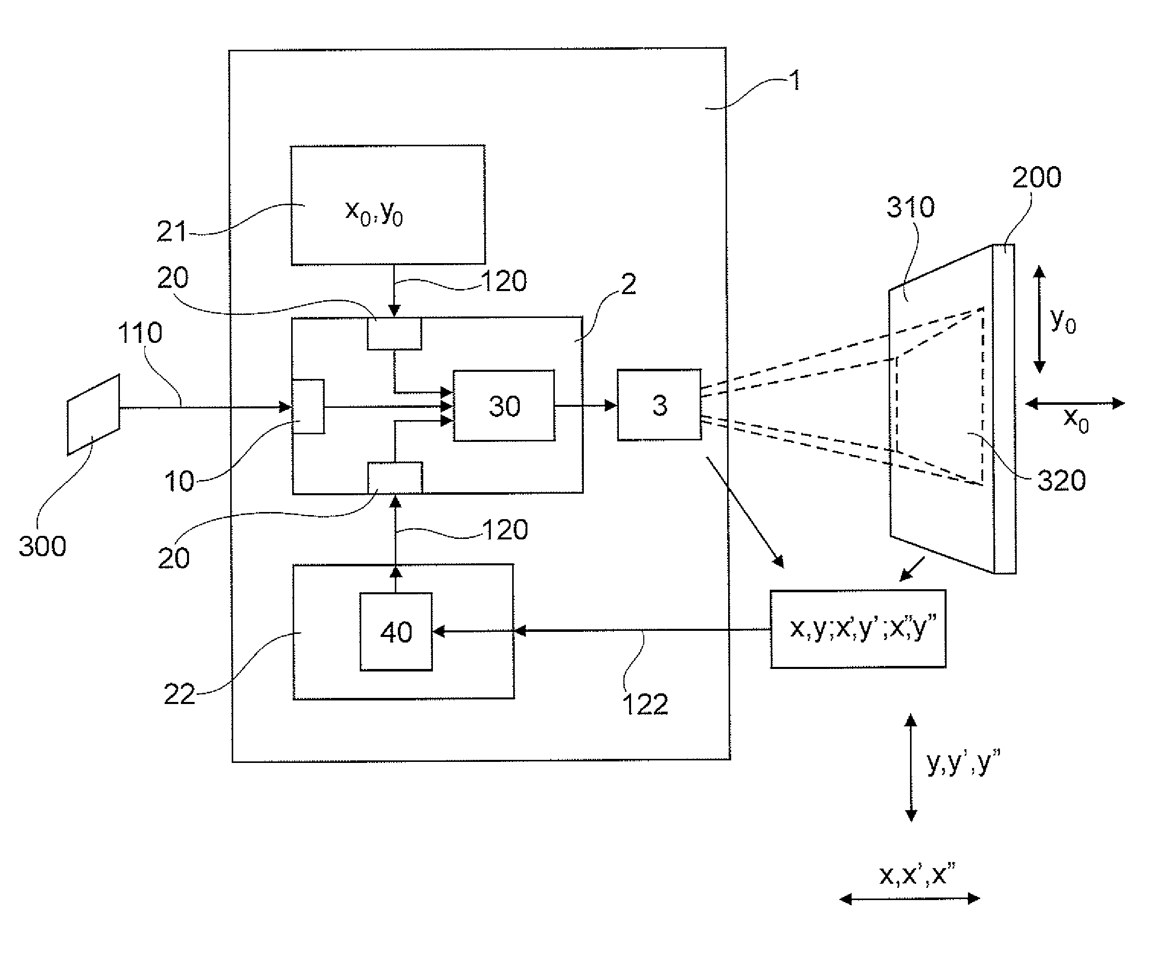
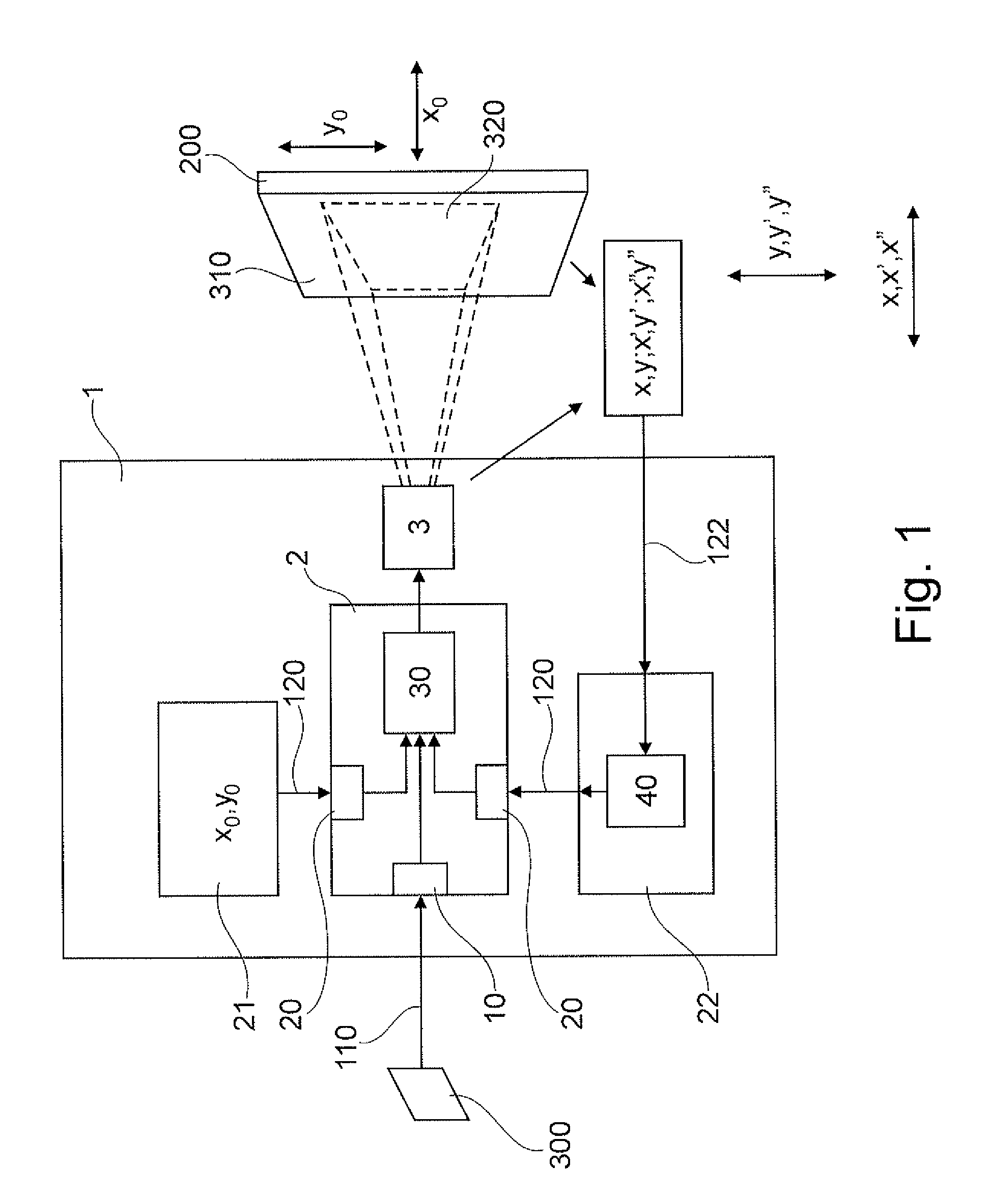
[0051]FIG. 1 shows a diagrammatic view of an exemplary embodiment of the invention. The image projection device 1 has an image adjustment device 2, an image projection or image display device 3, an input device 21 as well as a position-time state acquisition device 22. Let it be noted at this juncture that just an input device 21 or only a position-time state acquisition device can be provided, for example, so that an input device 21 and position-time state acquisition device 22 need not be provided at the same time. The input device 21 makes it possible to manually enter a desired position, in which the image 300 to be displayed is to be displayed on a display surface 200, for example. A desired position can here be an image alignment, but also an image distortion, which need not be limited solely to stretching with respect to height and width. Rather, a preliminary distortion can also be provided, for example, to enable an adjustment of the image 300 to be displayed to a curved projection surface 200.
[0052]The input device can here be adapted in such a way that corresponding image adjustment information 120 can be manually entered, for example via a keyboard.
[0053]The position-time state acquisition device 22 can here be adapted in such a way as to acquire position-time state information in the form of a position x, y, a movement x′, y′ or acceleration x″, y″. The type of state information used in a specific case depends on the kind of sensors used, in particular on whether the case involves a position sensor, a velocity sensor or an acceleration sensor. The corresponding position, velocity and acceleration data are here primarily recorded in directions involving the image plane of the image 300 to be displayed. Of course, a position, velocity or acceleration can take place in the direction lying perpendicular to the image plane, for example so that the focus and sharpness of an image to be projected can be adjusted and set.
[0054]The state information 22 acquired with sensors not depicted here is processed with an evaluation device 40, for example, in such a way that an image adjustment information 120 based on position-time state information 122 can be provided at the second input 20. The image adjustment information 120 provided at the second inputs 20 by either the acquisition device 21 and/or the position-time state acquisition device 22 can then be used as the basis for controlling an image display device 3 via a control device 30. The control device 30 is here provided with image information 110 for an image 300 to be displayed via a first input 10. The projection device 3 then projects the image 300 to be displayed on the display surface 200 or projection surface. The display 320 must here not fill the projection surface 200 completely, but a corresponding selection can be made with the acquisition device 21 to adjust the projection in such a way as to optimally utilize the projection surface.
[0055]For example, the projection device 3 can be a projector with a pixel arrangement or pixel panel that exhibits a plurality of pixels 103, as shown on FIG. 2. The entire pixel surface 322 can here have a diminished area 323 used for projection purposes. Possibilities include pixel panels in the form of backlit pixel panels or reflection pixel panels, e.g., of the kind used in DLP technology.
[0056]Given the use of an only diminished area 323 for example, if the diminished area 323 vibrates, the diminished area 323 can be subjected to shifted control within the framework of the overall surface 322, so that a vibration can be countered accordingly. If the vibration is assumed to be acting exclusively in a vertical direction by an amplitude corresponding roughly to an excursion corresponding to one pixel, the pixels are each controlled, increased or decreased by one row at the same frequency at which the vibration appears, so that the vibration is countered by a corresponding offsetting effect, and the display of an image 300 to be displayed on a display surface 200 remains essentially unchanged. At a greater excursion, the chronological control is adjusted to the acquired course of vibration in terms of amplitude and frequency, so that at most an erroneous display measuring on the order of a half pixel spacing takes place given an optimal regulation or control.
[0057]The use of a diminished area 323 reduces the so-called native resolution of the overall area 322 with a width of 320x or height of 320y by the corresponding buffer areas 321x in width and 321y in height, wherein these buffer areas are available in a width of 321x and 321y for offsetting a vibration, for example. The width of the buffer areas 321x and 321y is best designed for the maximum expected vibration level.
[0058]The use of a pixel panel makes it possible to realize a projection device with essentially no larger moving parts, wherein a corresponding image stabilization is achieved by a reduced resolution in a diminished pixel area 323 relative to the overall area 322.
[0059]FIG. 3 shows an exemplary embodiment of an aircraft with an image projection system 1 according to the invention and an associated projection surface 200. Let it be noted that several projection devices or image and film projection devices 1 according to the invention can also be provided in an aircraft, as well as in a ship or road vehicle (not shown).
[0060]FIG. 4 shows a diagrammatic view of a procedural sequence according to an exemplary embodiment of the invention. For example, image information for an image 300 to be displayed is acquired in a step S10, so that this image to be displayed can be reproduced on a display surface 200. In step S20, image adjustment information is generally received and/or acquired. This image adjustment information can consist of the entry of a desired position x0, y0 of the image 300 to be displayed, for example, which is used among other things to stipulate the position and size with which an image 300 to be displayed is to be shown on a display surface 200. Further, image adjustment information can also be provided in the form of position-time state information 122 in step S22. This position-time state information can be evaluated in step S40, for example, so that image adjustment information can be provided in step S20 based on the position-time state information. Based on the image adjustment information from step S20 and the image information acquired in step S10, an image display device can be controlled in step S30 in such a way as to adjust a desired image display using the image information and image adjustment information. As part of step S30, for example, pixels 103 of an image display device 3 can be controlled in step S33, for example pixels of a pixel panel. The pixel control described in conjunction with FIG. 2 makes it possible to adjust the image accordingly without larger, mechanically moving parts (of course, except for the structural design underlying DPL technology, for example), so that the image displayed on a display surface 300 remains essentially unchanged.
[0061]It should be noted that the described steps need not be taken in this exact sequence, but rather can be performed in a modified sequence whenever possible or sensible.
[0062]It should be noted that both the device and/or devices as well as the methods along with the computer program and computer-readable medium can be used not just in aircraft, but also in other vehicles, in which an image must be correspondingly adjusted during image display, in particular projections. Of course, such a device or method can also be used in cases involving projection devices that are fixed, but still might be exposed to an elevated vibration influence.
[0063]In addition, let it be noted that “encompassing” does not preclude other elements or steps, and that “an” or “one” does not preclude a plurality. Let it further be noted that features or steps described with reference to one of the above exemplary embodiments can also be used in combination with other features of steps in other exemplary embodiments described above. Reference numbers in the claims are not to be regarded as limiting.
PUM


Description & Claims & Application Information
We can also present the details of the Description, Claims and Application information to help users get a comprehensive understanding of the technical details of the patent, such as background art, summary of invention, brief description of drawings, description of embodiments, and other original content. On the other hand, users can also determine the specific scope of protection of the technology through the list of claims; as well as understand the changes in the life cycle of the technology with the presentation of the patent timeline. Login to view more.