
Loupe and lighting assembly for camera sensor dust detection

a technology for camera sensor and loupe, which is applied in the field of assembly of loupe and lighting means, can solve the problems of ordinary magnification without focused light not being able to help inspection of the camera sensor surface, sensor will be exposed to the atmosphere and airborne impurities, and ordinary magnification without focused light cannot solve the problem of enhancing the detection and/or characterization of dust particles, enhancing the detection and/or characterization of particulate contaminants, and enhancing the detection and/or characterization

Inactive Publication Date: 2010-07-29
1317442 ALBERTA
View PDF7 Cites 8 Cited by
  • Summary
  • Abstract
  • Description
  • Claims
  • Application Information

AI Technical Summary

Benefits of technology

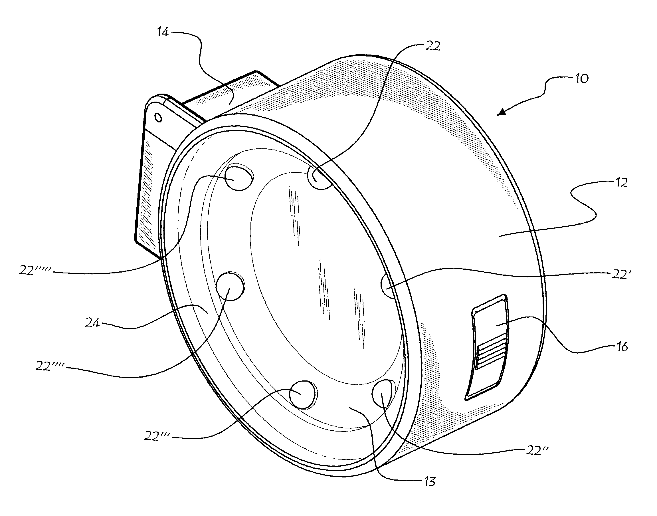
[0010]Furthermore, the configuration of lamps preferably comprises an even number of lamps which are strategically disposed to produce a 3 dimensional effect of the particles remaining onto the camera sensor surface, thus enhancing detection and / or characterization of the dust particles. In other words, illumination of an object from an overlying position will end up with a diffuse halo of shade, while illumination at different angles will generate a more realistic form as explained in the configuration herein after. This invention intends to make that task quicker and more users friendly when compared to traditional means of accomplishing the same task like the f22 test, as described above.
[0011]The present invention thus relates to a loupe and lighting assembly for enhancing detection of particulate contaminants on a planar surface, said assembly comprising a power source, a main frame body, light emitting means carried by said frame and operatively connected to said power source and a loupe lens also carried by the main frame, said light emitting means having means for generating a 3 dimensional effect over the particulate contaminants on the planar surface, wherein enhanced detection and characterization of the particulate contaminants is achieved.
[0026]In another embodiment, a manual trigger switch is provided to said main frame body and operatively connected to said power source and to said light emitting means, said trigger switch enabling the user to selectively activate said loupe and lighting assembly only when required and thus preventing unnecessary use of said power source.
[0031]d) orienting and positioning said loupe and lighting assembly in such a fashion as to enable enhanced detection and characterization of dust contaminants on the sensor.

Problems solved by technology

Of course, this sensor must remain as clean as possible, since impurities deposited thereon can undesirably alter the final image acquired by the camera.
It is inevitable that during normal use of a digital camera, its sensor will become exposed to the atmosphere and its airborne impurities, such as minute airborne dust particles.
More particularly, on digital cameras having interchangeable lenses such as digital single-lens reflex (DSLR) cameras, the sensor inevitably becomes exposed to the atmosphere and its impurities whenever the lens is removed from the body of the camera, for example when switching lenses.
Consequently, this method may require several picture takings and computer application work to bring out the contrast of blur spots on the photography.
It is noted that ordinary magnification without focused light can't help with inspecting the camera sensor surface, since the camera sensor location is deep within the camera frame and ambient light reach this location only minimally.
Also, the inspection light can't shine on the sensor directly without causing possibly irreparable damage.

Method used


Image

  • Loupe and lighting assembly for camera sensor dust detection
  • Loupe and lighting assembly for camera sensor dust detection
  • Loupe and lighting assembly for camera sensor dust detection

Examples


Embodiment Construction

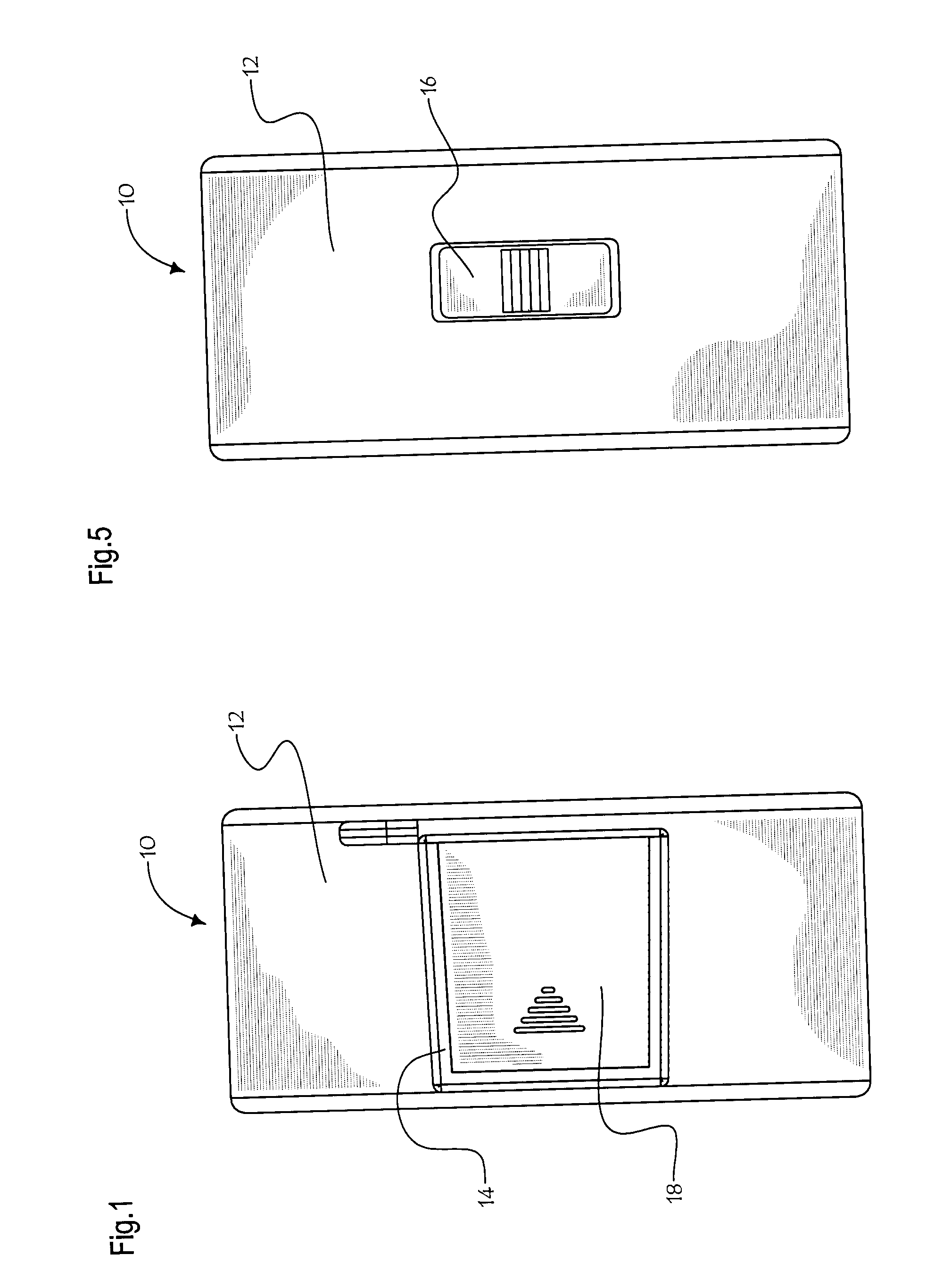
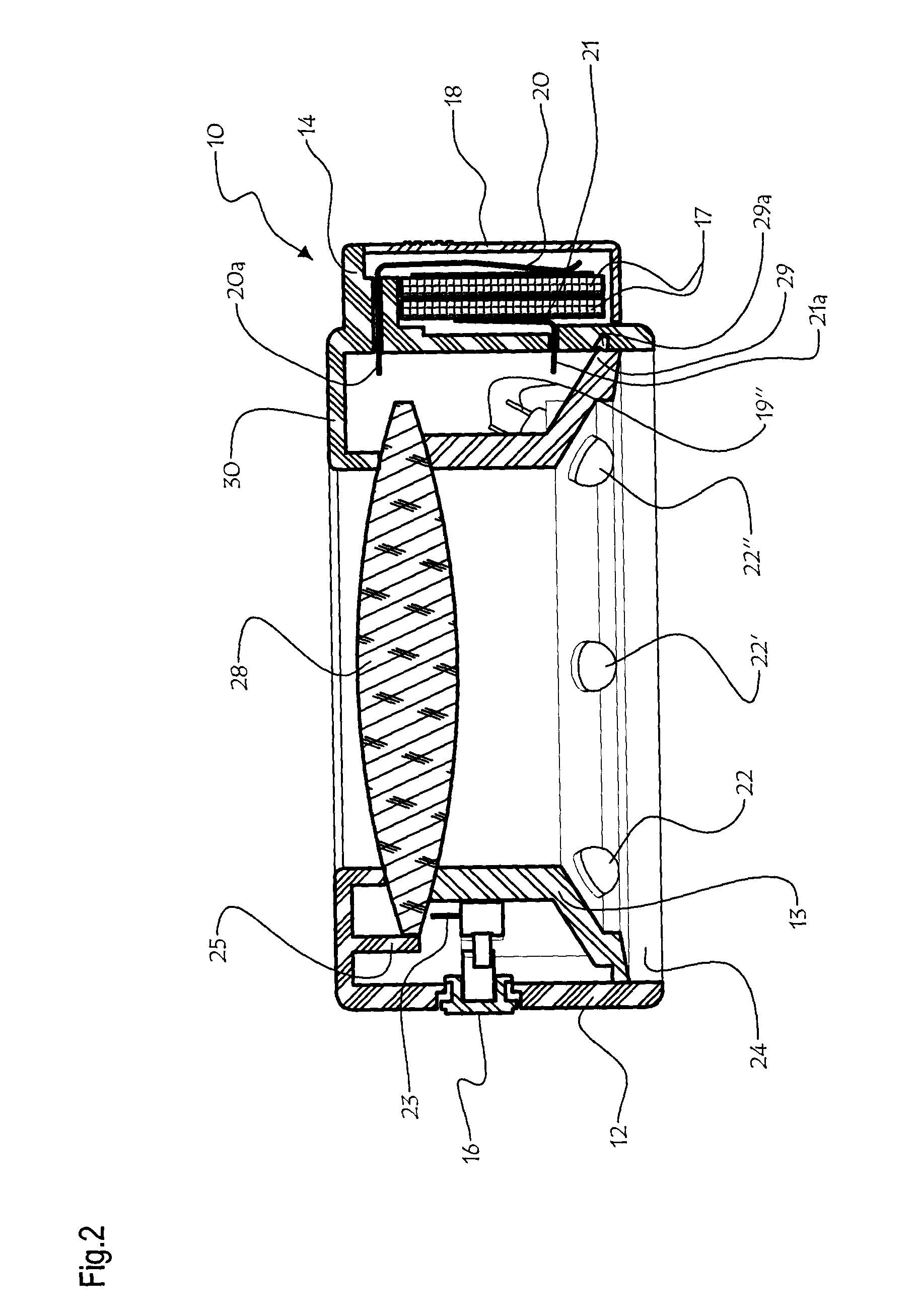
[0042]FIGS. 1, 3-5, 7a and 7b generally show a loupe and lighting assembly for camera sensor dust detection 10, according to the present invention, used to enhance detection and characterization of particulate contaminants on a camera sensor. This loupe and lighting assembly comprises a hollow-centered cylindroid main frame body 12, comprising a battery housing 14 containing the batteries 17 needed to power the lights of the invention and covered by a sliding cover 18 with embossed notches providing a better grip and enabling easier access. Upon the main frame body 12 is also integrated a manual trigger switch 16 allowing a selective powering of the loupe and lighting assembly and thus preventing depletion of the batteries 17 when the invention is not in use, with embossed notches for a better grip. Radially and inwardly within the cylindroid main frame body 12 is fastened a smaller hollow-centered cylindroid body with a conic flange 13 (better seen on FIGS. 2, 6 and 7c) upon which ...


PUM


Abstract

A loupe and lighting assembly for enhancing detection of dust particles on the optical sensor of a digital camera. The assembly is made of a cylindroid hollow-centered main frame body, into which is fixed a loupe lens. A battery housing is joined to the body in order to supply electrical power to a LED array. The LED array is made from a plurality of LED diodes mounted peripherally and around the inside of the cylindroid body, being tilted at an acute angle from the axis orthogonal to the plane of the cylindroid body so that all diodes axially converge toward a single focal point, at a certain distance from the main frame body. The dust particles scattered upon the sensor become clearly visible to an observer looking through the assembly when the dust particles location coincide with the LED common focal point.

Description

CROSS-REFERENCE DATA[0001]The present application claims Paris convention priority based upon U.S. provisional patent application No. 60 / 934,263 filed Jun. 12, 2007.FIELD OF THE INVENTION[0002]The present invention relates to an assembly of a loupe and lighting means that can be used to enhance detection of dust particles on the sensor of digital cameras.BACKGROUND OF THE INVENTION[0003]Digital cameras comprise a sensor chamber in which is lodged an electronic sensor, such as a charge-coupled device (CCD) sensor or Complementary Metal Oxide Semiconductor (CMOS) sensor, onto which is projected the image of what is seen through the lens of the camera. This sensor can acquire the image projected thereon and convert it into electronic data, which is thereafter forwarded to data processing means provided on the digital camera. The data processing means then converts this electronic data into an image file of known format, such as in JPEG, TIFF or RAW formats, stored thereafter on the mem...

Claims


Application Information

Patent Timeline
Patent Type & Authority Applications(United States)
IPC IPC(8): F21V33/00
CPCG01N21/94H04N17/002G03B17/56G02B25/02G03B43/00
Inventor RAHBAR-DEHGHAN, FARIBORZ
Owner 1317442 ALBERTA
Learn More