Radio receiving device

a technology for receiving devices and radios, applied in the direction of digital transmission, amplitude demodulation, pulse technique, etc., can solve the problems of image frequency signals that interfere with the demodulation of desired signals, image frequency signals that interfere with the above-described rf filters, and increase the size of above-described filters, etc., to achieve the effect of suppressing image interference in a short period of tim

Active Publication Date: 2010-07-29
PANASONIC CORP
View PDF9 Cites 32 Cited by
  • Summary
  • Abstract
  • Description
  • Claims
  • Application Information

AI Technical Summary

Benefits of technology

[0064]As described above, according to the present invention, a radio receiving apparatus capable of making compensation for both amplitude variations...

Problems solved by technology

On the other hand, the heterodyne system has a problem of interference caused by an image frequency signal.
Accordingly, the image frequency signal interferes with demodulation of the desired signal.
However, the above-described RF filter increases in ...

Method used


Image

  • Radio receiving device
  • Radio receiving device
  • Radio receiving device

Examples


first embodiment

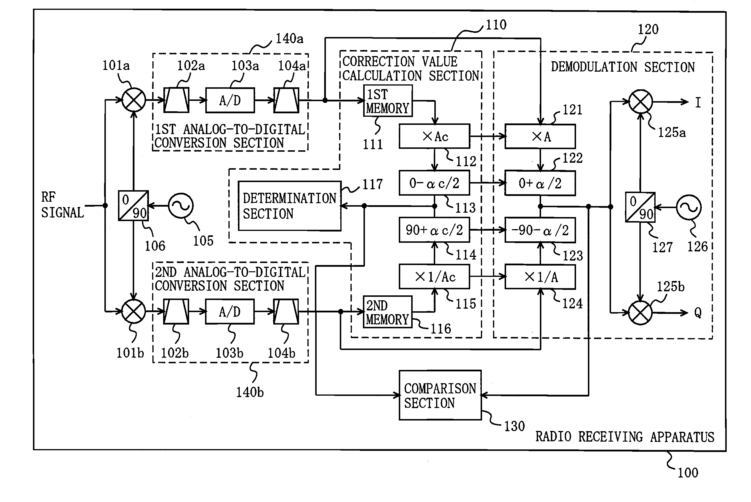
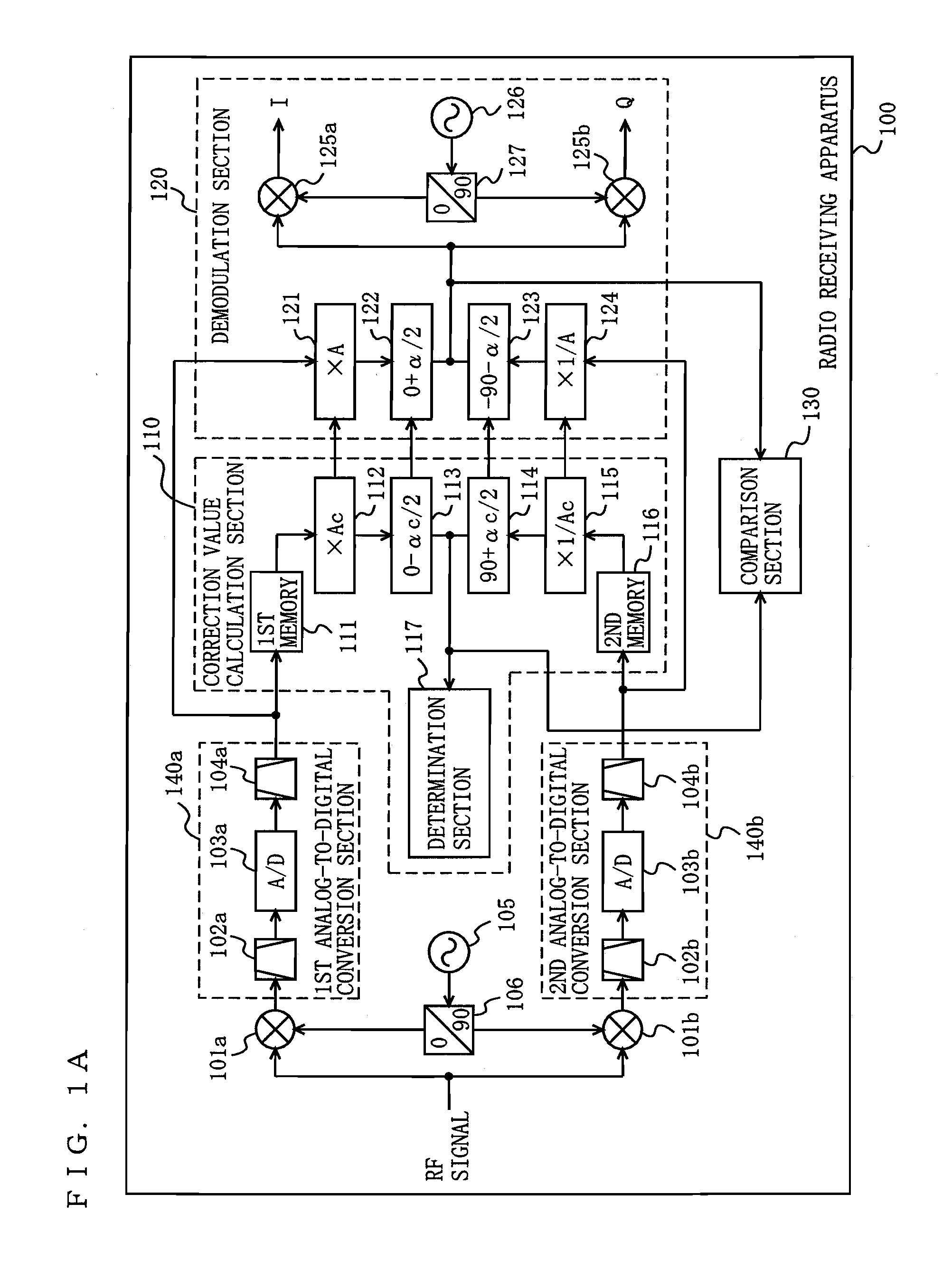
[0132]FIG. 1A is a block diagram showing a functional structure of a radio receiving apparatus 100 according to a first embodiment of the present invention. In FIG. 1A, the radio receiving apparatus 100 includes a first down-converter 101a, a first analog-to-digital conversion section 140a, a second down-converter 101b, a second analog-to-digital conversion section 140b, a local oscillator 105, a first 90-degree phase shifter 106, a correction value calculation section 110, a demodulation section 120, and a comparison section 130.

[0133]The first analog-to-digital conversion section 140a includes a first antialiasing filter 102a, a first analog-to-digital converter 103a, and a first channel selection filter 104a.

[0134]The second analog-to-digital conversion section 140b includes a second antialiasing filter 102b, a second analog-to-digital converter 103b, and a second channel selection filter 104b.

[0135]The correction value calculation section 110 includes a first memory 111, a fir...

second embodiment

[0164]FIG. 1A is used for showing a radio receiving apparatus, according to a second embodiment, which is similar in structure to that according to the first embodiment. The second embodiment is different from the first embodiment in calculation algorithm used in the correction value calculation section 110. FIG. 3 is a diagram for illustrating a calculation algorithm used in the correction value calculation section 110 of the radio receiving apparatus 100 according to the second embodiment of the present invention.

[0165]In the first embodiment, the correction value calculation section 110 selects the amplitude correction candidate value Ac and the phase correction candidate value αc from the predetermined ranges and obtains the first combined signal by two-dimensional matrix calculations, so as to obtain the inflection point. However, it requires a large amount of memory to perform two-dimensional matrix calculations.

[0166]In the second embodiment, the determination section 117 of ...

third embodiment

[0172]FIG. 1A is used for showing a radio receiving apparatus, according to a third embodiment, which is similar in structure to that according to the first embodiment. The second embodiment is different from the first embodiment in calculation algorithm used in the correction value calculation section 110. FIG. 5 is a diagram for illustrating a calculation algorithm used in the correction value calculation section 110 of the radio receiving apparatus 100 according to the third embodiment of the present invention.

[0173]In the first embodiment, the correction value calculation section 110 selects the amplitude correction candidate value Ac and the phase correction candidate value αc from the predetermined ranges and obtains the first combined signal by two-dimensional matrix calculations, so as to obtain the inflection point. However, it requires a large amount of memory to perform two-dimensional matrix calculations.

[0174]In the second embodiment, the determination section 117 of th...


PUM


Abstract

A radio receiving apparatus capable of making compensation for both amplitude variations and phase variations and of suppressing image interference in a short period of time is provided.
A correction value calculation section (110) combines a signal, obtained by multiplying a first digital signal by an amplitude correction candidate value and rotating the phase of the first digital signal, with a signal obtained by multiplying a second digital signal by a multiplicative inverse of the amplitude correction candidate value and performing, for the second digital signal, phase rotation which is in a quadrature relationship to phase rotation performed for the first digital signal, so as to obtain a first combined signal, obtain an inflection point of the first combined signal, and input, to a demodulation section (120), the amplitude correction candidate value and a phase correction candidate value, which correspond to the inflection point, as an amplitude correction value and a phase correction value, respectively. The demodulation section (120) makes compensation for the amplitudes and the phases and suppresses image interference, based on the amplitude correction value and the phase correction value.

Description

TECHNICAL FIELD[0001]The present invention relates to a radio receiving apparatus used for a mobile terminal, and more particularly to a radio receiving apparatus capable of suppressing an image frequency signal.BACKGROUND ART[0002]In recent years, a mobile terminal is explosively widespread. A radio circuit thereof is required to be miniaturized. A radio receiving apparatus has two main types: one employing a homodyne (direct conversion) system and the other employing a heterodyne system. The heterodyne system is widely used for a mobile terminal, since the heterodyne system does not have problems of DC offset, 1 / f noise, AM suppression, and the like, each of which is major interference in the homodyne system. On the other hand, the heterodyne system has a problem of interference caused by an image frequency signal.[0003]FIG. 11 is a diagram showing a mechanism of interference caused by an image frequency signal. As shown in FIG. 11, the image frequency signal is present on the opp...

Claims


Application Information

Patent Timeline
IPC IPC(8): H04B1/26H04L27/06
CPCH04B1/28H04L27/3836H04L27/3809
Inventor NAKATANI, TOSHIFUMI
Owner PANASONIC CORP
Why Eureka
Try Eureka