Method and System for Changing Image Density and Contrast

a technology of density and contrast, applied in image enhancement, image analysis, instruments, etc., can solve the problems of inability to accurately select a subrange of pixel values to be enhanced, and the dependence between density and contrast adjustmen

Active Publication Date: 2010-07-29
AGFA NV
View PDF11 Cites 10 Cited by
  • Summary
  • Abstract
  • Description
  • Claims
  • Application Information

AI Technical Summary

Benefits of technology

[0021]The methods in accordance with the present invention are applicable to any kind of monochrome digital images as well as to colour images. To this end, the colour images comprising three components for each pixel, commonly representing the red, green and blue channel inputs of video equipment (RGB), are preferably converted into a standard colour space that represents hue, saturation and luminance (HSL). If an image is represented in this colour space, then the methods in accordance with the present invention are preferably applied to the luminance component only, as if it were a monochrome image. If only this channel is affected, then the contrast and density can be adjusted without introducing colour distortions.

Problems solved by technology

The disadvantage is the dependency between density and contrast adjustment.
However, this method is not suited to accurately select a subrange of pixel values to be enhanced.

Method used


Image

  • Method and System for Changing Image Density and Contrast
  • Method and System for Changing Image Density and Contrast
  • Method and System for Changing Image Density and Contrast

Examples


second embodiment

[0096]In a second embodiment, the amount of density and contrast adjustment by the first enhancement method and the amount of density and contrast adjustment by the second enhancement method are deduced from the current state of a single indicium.

[0097]Preferably the deviation from the initial position (reference position) of the indicium is used to deduce the relative amounts of adjustments established by both enhancement methods. Small density and contrast adjustments are established by the second enhancement method. The larger the deviation, the more the first enhancement method is used.

[0098]An example of a weighting function establishing this relationship is the tangens hyperbolicus function:

dc=x*dx and dw=(1−x)*dx with x=tan h(c*dx) and c a scaling factor

dg=y*dy and dl=(1−y)*dy with y=tan h(c*dy) and c a scaling factor

[0099]Another possibility is to establish the adjustments by the second enhancement method until a maximum amount of contrast and density change by the second en...

third embodiment

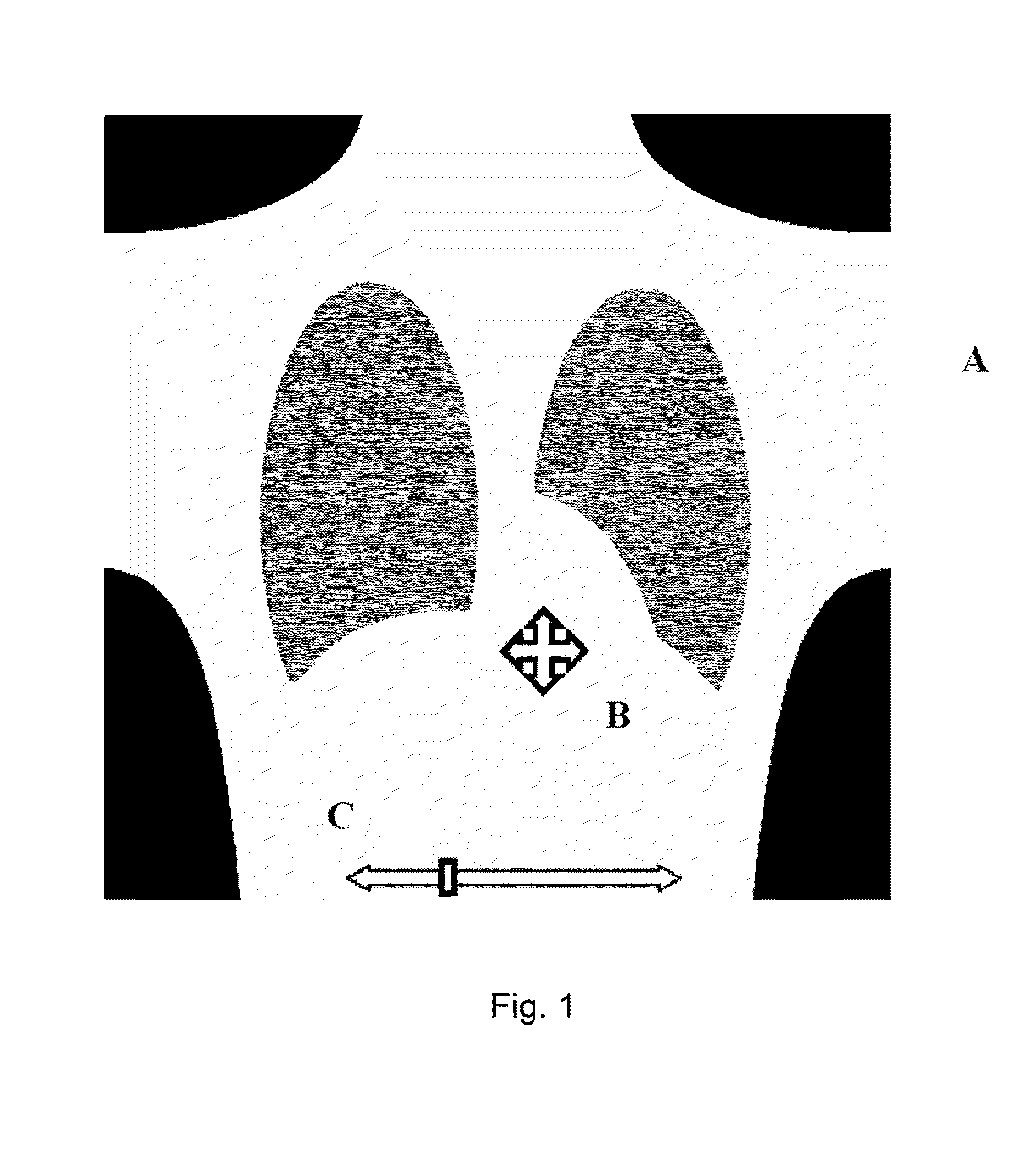
[0100]In a third embodiment, the amount of density and contrast adjustment by the first enhancement method and the amount of density and contrast adjustment by the second enhancement method are deduced from the trajectory of an indicium.

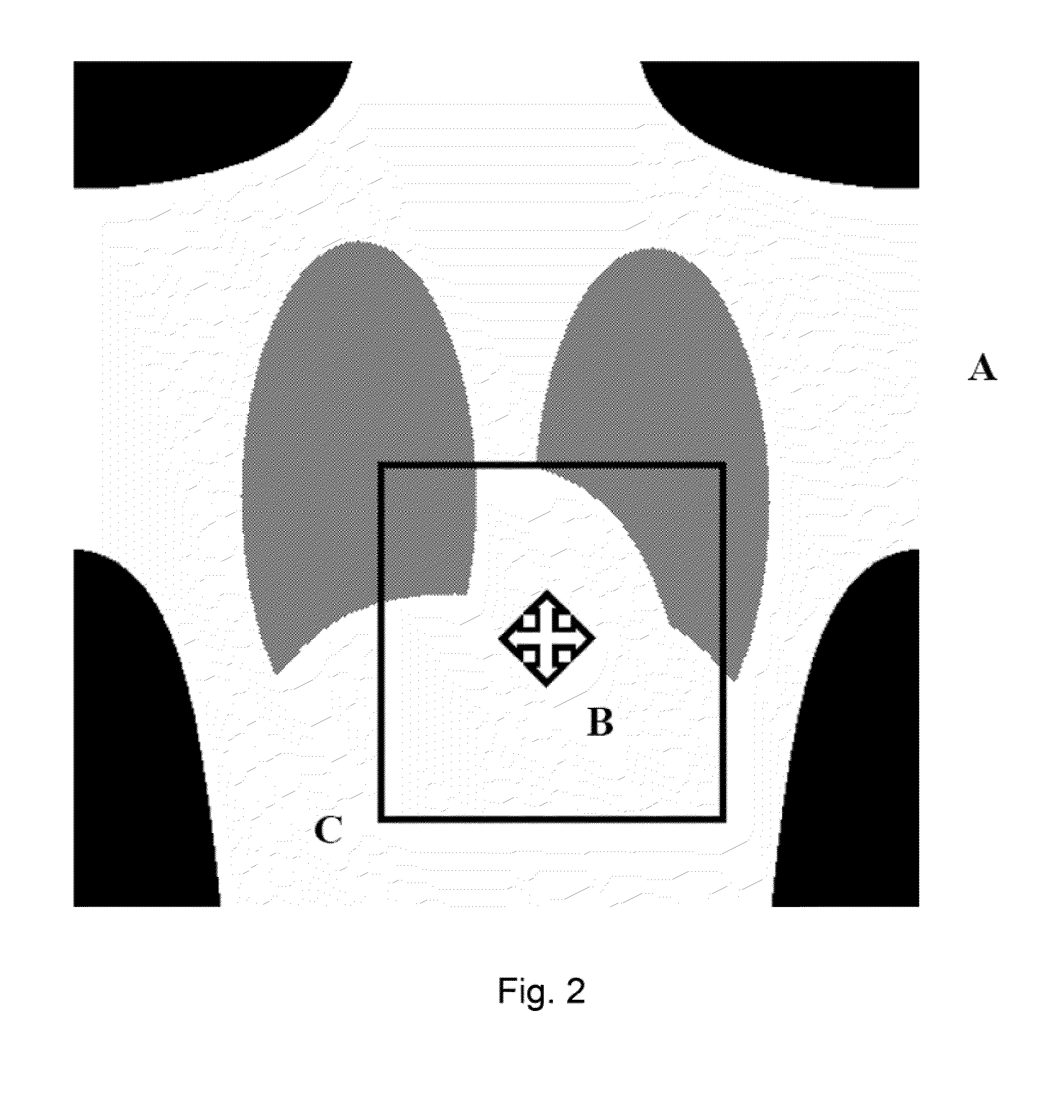
[0101]Preferably the direction of movements of this indicium is used to deduce the relative amounts of adjustments established by both enhancement methods. As long as the user moves the indicium (e.g. the cursor) into the same direction, the amount of adjustment by the first enhancement method is gradually increasing and the amount of adjustment by the second enhancement method is gradually decreasing.

[0102]As the user starts moving the cursor into the opposite directions, the further adjustments are first established by the second enhancement method.

[0103]Moving the cursor into the same direction is defined as a constantly increasing or decreasing of the required density or contrast adjustment dy and dx . Moving the cursor into the opposite directio...

fourth embodiment

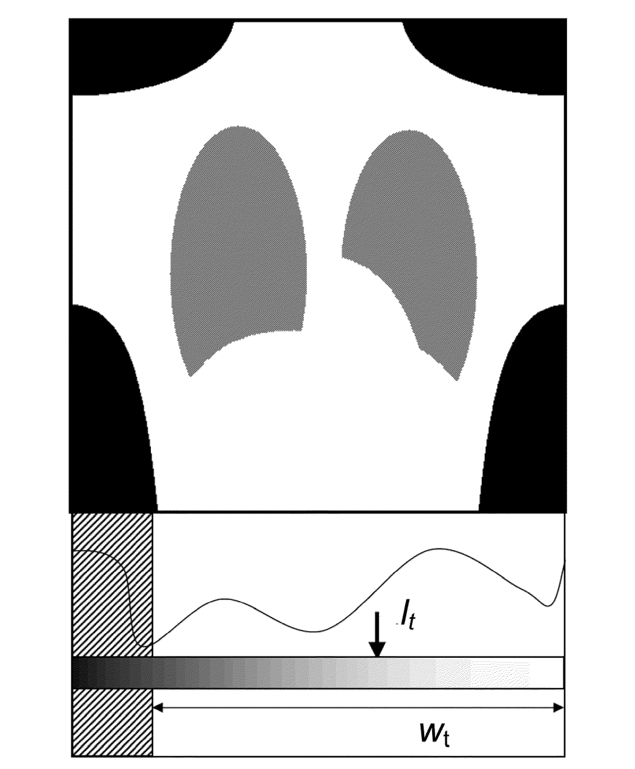
[0105]In a fourth embodiment, the amount of density and contrast adjustment by the first enhancement method is computed to approximate a target window width / level setting.

[0106]Referring to FIG. 3, the adjustment vector (dx, dy) resulting from the deviation of the current position of the first indicium from the initial position (wi, / ) at the start of the interactive adjustment session, is decomposed into a first adjustment vector along the direction to a target window width / level setting (wt, i) and a second adjustment vector, preferably orthogonally to the first one, the sum of both adjustment vectors being equal to the adjustment vector (dx, dy). The first adjustment vector specifies the amount of contrast and density change resulting from the first enhancement method (dw, dl) and the second adjustment vector specifies the amount of contrast and density change resulting from the second enhancement method (dc, dg).

[0107]FIG. 4

[0108]Alternatively, referring to FIG. 4, the adjustment...


PUM


Abstract

At least one of two enhancement methods for changing contrast and/or density are applied to an image. According to a first enhancement method the window width/level settings of the image are modified and according to a second enhancement method density and contrast of the image are modified by modifying a multi-scale representation of the image whereby modification is derived from at least two gradient functions determined at different scales, a gradient function at a specific scale specifying the dependency of contrast amplification at said scale as a function of density. The amount of modification obtained by applying either of said first and second enhancement methods is determined by the amount of movement of at least one indicium.

Description

RELATED APPLICATIONS[0001]This application claims priority to European Patent Application No. EP 08170064.3 filed on Nov. 27, 2008, and claims the benefit under 35 USC 119(e) of U.S. Provisional Application No. 61 / 118,498, filed on Nov. 28, 2008, both of which are incorporated herein by reference in their entirety.BACKGROUND OF THE INVENTION[0002]In a typical medical workstation the appearance of a displayed image can be adjusted by selecting a relevant subrange of the image's grey value pixel data and converting the data in this subrange according to a specific gradation function.[0003]An interactive method to adjust manually the width and the position of the selected subrange is commonly known as window width / level adjustment.[0004]Such a transformation of grey value pixel data is mainly used to increase the contrast in some regions of the image or in a selected subrange of the grey value pixel data. The price to be paid is decreased contrast in other parts of the image and other ...

Claims


Application Information

Patent Timeline
Patent Type & Authority Applications(United States)
IPC IPC(8): G06K9/40G06F3/048
CPCG06T2200/24G06T2207/10116G06F3/04847G06T2207/30004G06T5/009G06T2207/20016
Inventor BERTENS, TOMVUYLSTEKE, PIETER
Owner AGFA NV
Why Eureka
Try Eureka