Flexible and Static Interspinous/Inter-Laminar Spinal Spacers

a spine and spacer technology, applied in the field of spine devices, can solve problems such as depression, general physical deterioration, nerve compression,

Active Publication Date: 2010-07-29
LIFE SPINE INC
View PDF8 Cites 43 Cited by
  • Summary
  • Abstract
  • Description
  • Claims
  • Application Information

AI Technical Summary

Benefits of technology

[0016]The present flexible spinal spacers allow for controlled movement of the adjacent vertebrae to which it is attached, as well as aid in insertion and / or implantation of the flexible spinal spacer.

Problems solved by technology

Such degenerative or age-related changes in our bodies can lead to compression of nerves (i.e. pressure on the nerves that can cause pain and / or damage).
Lack of activity because of lumbar spinal stenosis may lead to obesity, depression and general physical deterioration.
Other spinal conditions, diseases and / or accidents, however, can also cause problems that may require spinal surgery and the need to hold or stabilize adjacent vertebrae or vertebral parts in a spatial orientation relative to one another and / or with regard to other vertebral parts.

Method used


Image

  • Flexible and Static Interspinous/Inter-Laminar Spinal Spacers
  • Flexible and Static Interspinous/Inter-Laminar Spinal Spacers
  • Flexible and Static Interspinous/Inter-Laminar Spinal Spacers

Examples


Embodiment Construction

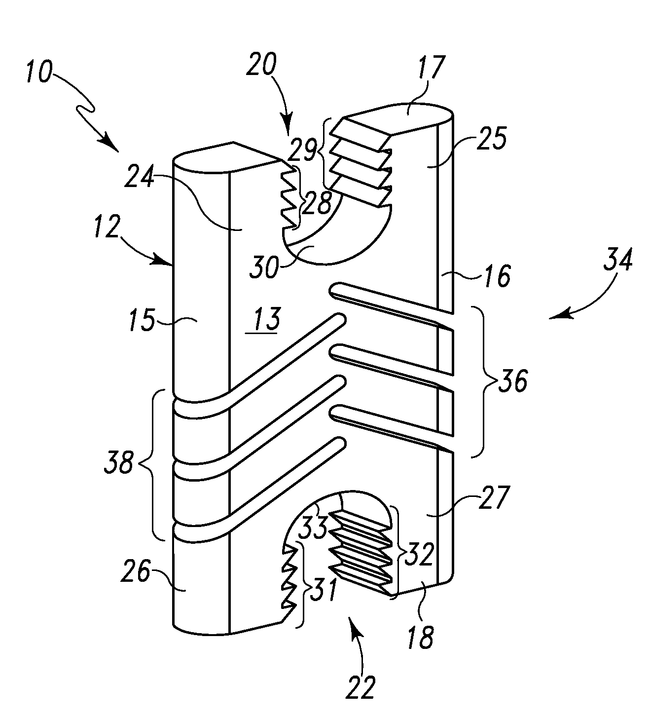
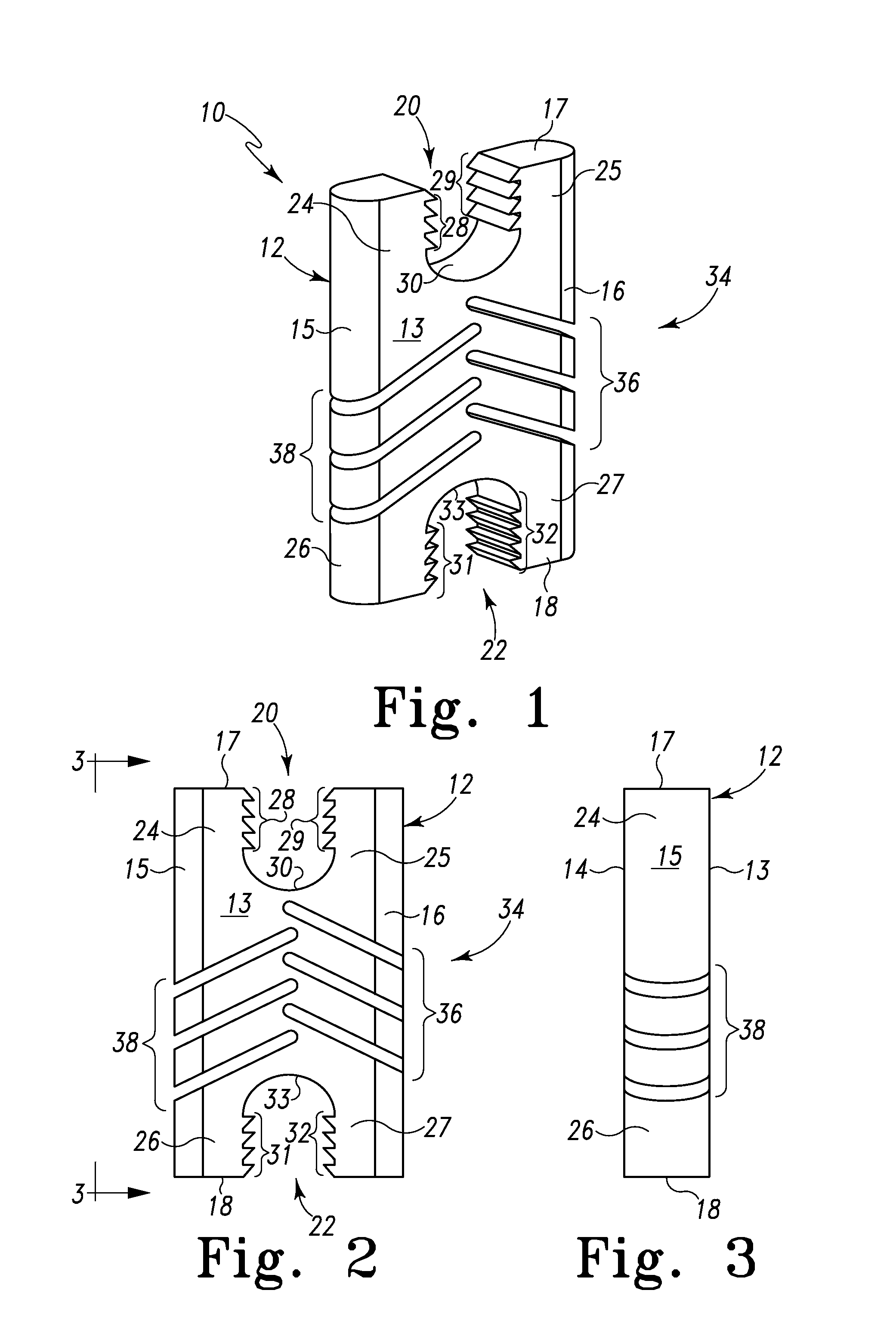
[0043]Referring to FIGS. 1-3, there is shown an embodiment of a flexible interspinous or inter-laminar spinal spacer (processes, transverse and spinous—i.e. flexible spinal spacer) generally designated 10 fashioned in accordance with the principles of the present invention. The flexible spinal spacer 10 is used as an interspinous, inter-laminar, interbody, or interbony spinal spacer and thus is configured to be placed between bony structures of adjacent vertebrae of a spine.

[0044]The flexible spinal spacer 10 is formed as a unitary or single-piece body 12 of a biocompatible material. The body 12 is formed in a generally “H” shape and thus defines a first lateral side 15, a second lateral side 16, a posterior side 13, an anterior side 14, a superior side or end 17, and an inferior side or end 18. It should be appreciated that the flexible spinal spacer may take forms other than an “H” while maintaining the features and / or characteristics of the present invention. The body 12 also has...


PUM


Abstract

Interspinous/inter-laminar spinal spacers (spinal spacers) are configured to be placed between bony structures (i.e. transverse and spinous processes) of adjacent vertebrae of a spine. In one form, flexible spinal spacers are defined by a unitary body that is configured to be placed between bony structures of adjacent vertebrae of a spine. The unitary body has a flex portion that provides for motion between the adjacent vertebrae to which it is coupled. The flex portion is configurable to provide for various degrees of angulation, flexion, extension and/or compression of the present flexible spinal spacer. In another form, static spinal spacers are defined by a unitary body that is configured to be placed between bony structures of adjacent vertebrae of a spine. The unitary body has saddle-shaped ends each defining a pocket that is configured to receive a bony structure of a vertebra. The pockets may or may not be textured and/or may or may not include teeth, serrations or ridged surfaces to secure the spinal spacer to the bony structure.

Description

RELATED APPLICATIONS[0001]This patent application claims the benefit of and / or priority to U.S. Provisional Patent Application Ser. No. 61 / 147,384 filed Jan. 26, 2009, entitled “Flexible Interspinous / Inter-Laminar Spinal Spacer” the entire contents of which is specifically incorporated herein by this reference.BACKGROUND OF THE INVENTION[0002]1. Field of the Invention[0003]The present invention relates to devices for the spine and, more particularly, to spinal implants for providing interspinous and / or inter-laminar space between adjacent vertebrae.[0004]2. Background Information[0005]As we age various changes can occur in the body. For instance, the ligaments of the spine can thicken and calcify (i.e. harden from deposits of calcium), bone and joints may enlarge, bone spurs called osteophytes may form, spinal discs may collapse and bulge (i.e. herniate) or one vertebra may slip over another (spondylolisthesis). Any one or these conditions and / or others can cause what is known as lu...

Claims


Application Information

Patent Timeline
Patent Type & Authority Applications(United States)
IPC IPC(8): A61B17/70
CPCA61B17/7062A61B2017/564A61B17/7068
Inventor BUCCI, KARA A.
Owner LIFE SPINE INC
Why Eureka
Try Eureka