Saddle-shaped annuloplasty ring

a technology of annuloplasty and saddle-shaped, which is applied in the field of prosthetic annuloplasty ring, can solve the problems of partial lvot obstruction, hemodynamic instability, and mitral regurgitation, and achieve the effects of improving the patient's quality of life, and improving the patient's comfor

Inactive Publication Date: 2008-03-06
EDWARDS LIFESCIENCES CORP
View PDF57 Cites 27 Cited by
  • Summary
  • Abstract
  • Description
  • Claims
  • Application Information

AI Technical Summary

Benefits of technology

[0014]In another embodiment of the invention, a mitral annuloplasty ring includes a closed and generally rigid ring body arranged around a flow axis having an upward direction and a downward direction. The downward direction corresponds to the direction of blood flow through the mitral valve annulus when the annuloplasty ring is implanted. The ring body exhibits, in top plan view along the flow axis, a relatively straight anterior segment substantially extending between two trigones and intended to be implanted against the anterior aspect of the mitral annulus. Two posterior segments join at a convex posterior apex and together define a posterior portion of the ring body intended to be implanted against the posterior aspect of the mitral annulus. In elevational view parallel to the reference plane, each of the anterior segment and the posterior portion has an upward bow therein relative to the two lowermost points of the ring, wherein the anterior segment bows upward farther from the reference plane than the posterior portion. In a preferred form, the ring body defines lowermost flat segments on opposite sides of the posterior portion in which are located the two lowermost points of the ring. The upward bow in the anterior segment is desirably between 1-2 mm higher than the upward bow in the posterior portion. Preferably, the magnitude of the posterior upward bow is between about 2.9-4.5 mm, and the magnitude of the anterior upward bow is between about 4-7 mm.

Problems solved by technology

This excess tissue, or redundancy, often prevents the anterior and posterior leaflets from properly coapting, resulting in mitral regurgitation.
This leads to partial LVOT obstruction and hemodynamic instability.
This scenario is not an uncommon incident following an otherwise successful mitral valve repair and can be very difficult to treat with existing repair techniques and devices, and may require mitral valve replacement rather than the preferred of valve repair.

Method used


Image

  • Saddle-shaped annuloplasty ring
  • Saddle-shaped annuloplasty ring
  • Saddle-shaped annuloplasty ring

Examples


Embodiment Construction

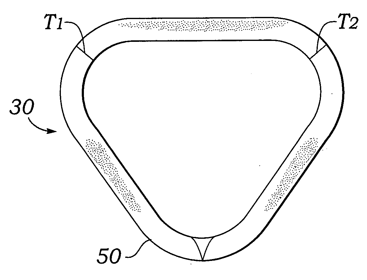
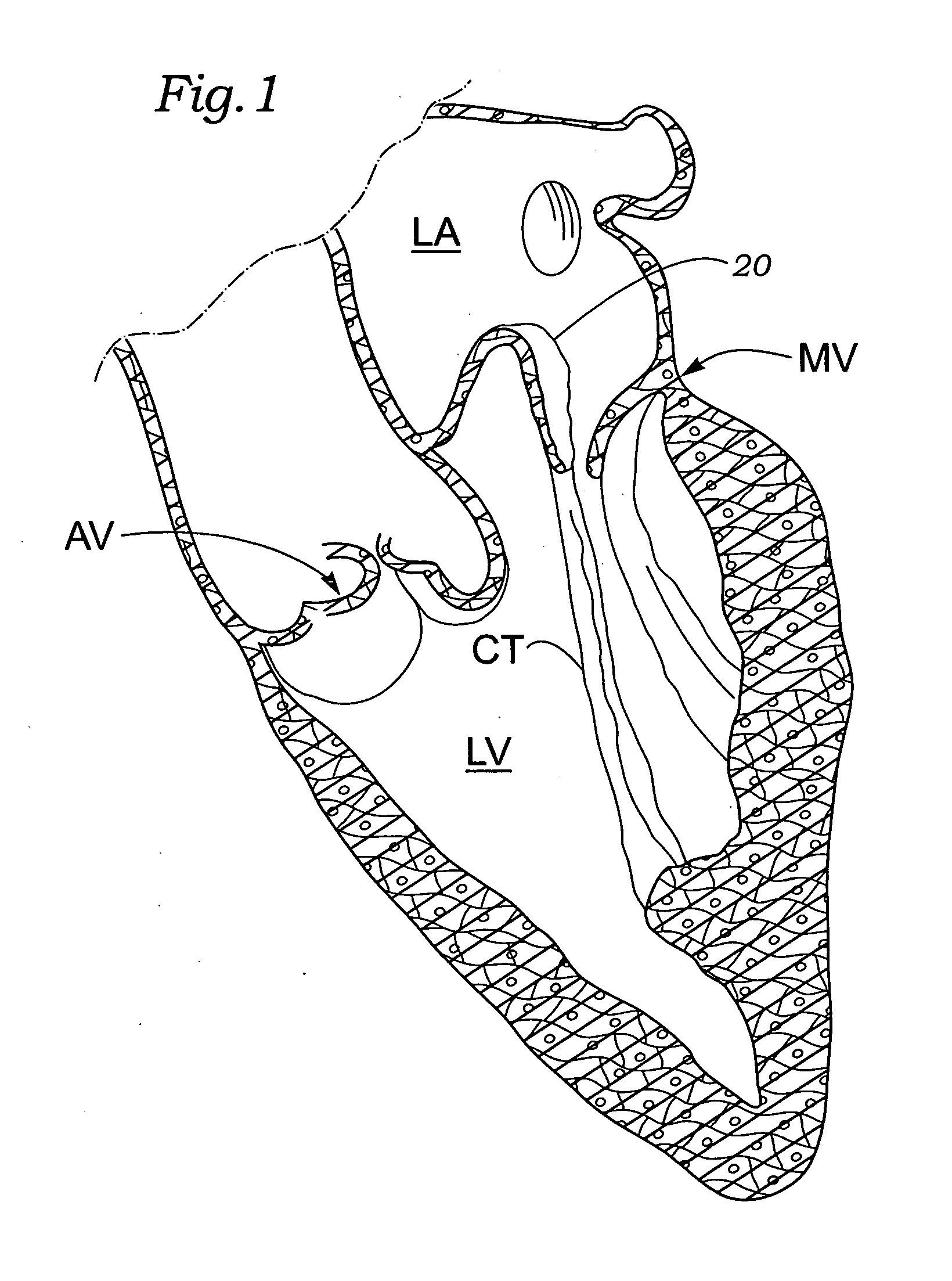
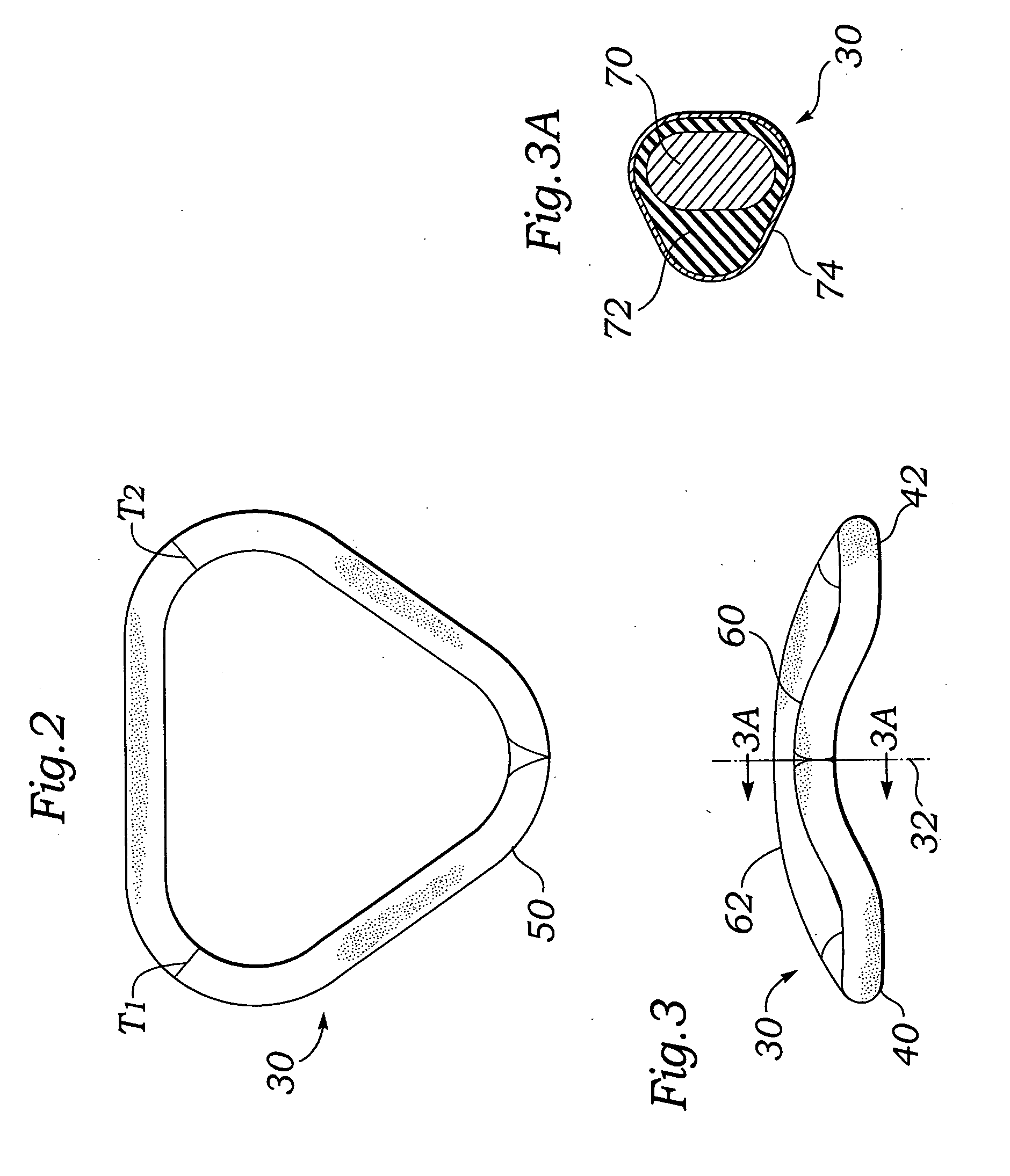
[0021]The present invention provides a novel annuloplasty ring for correcting pathologies associated with mitral valve prolapse, also known by a number of other names given above, including Barlow's syndrome. With this pathology, the mitral valve leaflets are distended (i.e., stretched, lengthened, swelled, thickened) or in general have become loose and floppy such that they do not properly coapt. In contrast to prior repair techniques, the annuloplasty ring of the present invention reduces or eliminates the need for a sliding annuloplasty. Furthermore, instead of attempting to constrict the mitral annulus by the addition of an annuloplasty ring that is under-sized with respect to the existing annulus, the present invention accommodates the excess material of the leaflets by providing a larger support ring than has previously been utilized. Typical annuloplasty support rings have a long or major dimension and a short or minor dimension, with the conventional ratio of the minor to ma...


PUM


Abstract

A mitral annuloplasty ring that has a saddle shape with an upward bow in both an anterior segment and a posterior portion, with the upward bow being more pronounced in the anterior segment. The ring defines a closed ring body with a rounded isosceles triangular shape and the anterior segment along a long side. The posterior portion bulges outward to create a minor-major axis dimension ratio of between about 3.3:4 to 4:4. An inner ring body is made of a generally rigid material such as titanium that will substantially resist distortion when subjected to the stress imparted thereon after implantation in the mitral valve annulus of an operating human heart. The outward and upward posterior bow of the annuloplasty ring corrects for pathologies associated with mitral valve prolapse, as seen with Barlow's syndrome for instance, in which the leaflets tend to be elongated or floppy. The anterior segment has an enhanced upward bow to conform to systolic mitral annulus shapes, and the upward posterior bow is somewhat lower, for example between 1-2 mm lower, to help reduce the chance of suture pull-out, or dehiscence.

Description

FIELD OF THE INVENTION[0001]The present invention refers to a prosthetic annuloplasty ring for a mitral valve, in particular for correcting pathologies associated with mitral valve prolapse, for example, Barlow's syndrome or myxomatous disease.BACKGROUND OF THE INVENTION[0002]In the operation of the heart, returning blood enters the right atrium and passes through the tricuspid valve into the right ventricle. From there, blood is pumped through the pulmonary valve and the pulmonary artery to the lungs. Oxygenated blood enters the left atrium and passes into the left ventricle through the mitral valve. Healthy mitral valve leaflets “coapt” or meet near the middle of the blood flow path and are attached to papillary muscles within the interior of the left ventricle by a number of stringy chordae tendinae. During systole, the mitral valve closes and the aortic valve opens, thus preventing blood from regurgitating into the left atrium and forcing blood into the aorta, and from there thr...

Claims


Application Information

Patent Timeline
Patent Type & Authority Applications(United States)
IPC IPC(8): A61F2/24
CPCA61F2/2448A61F2230/0063A61F2002/30199
Inventor INGLE, AARONADZICH, VASO
Owner EDWARDS LIFESCIENCES CORP
Why Eureka
Try Eureka