
Numerical control submerged automatic arc welding device and numerical control submerged automatic arc welding method for saddle-shaped narrow bevel

A submerged arc automatic welding, saddle-shaped technology, applied in arc welding equipment, welding equipment, manufacturing tools, etc., can solve the problems of low efficiency, manual adjustment, difficult to repair, etc., to achieve high quality and improve production efficiency.

Inactive Publication Date: 2010-07-21
HARBIN WELDING INST LTD
View PDF0 Cites 27 Cited by
  • Summary
  • Abstract
  • Description
  • Claims
  • Application Information

AI Technical Summary

Problems solved by technology

[0004] At present, most domestic manufacturers use manual welding, and only a few manufacturers use special welding machines, but the degree of automation is not high. The saddle-shaped movement of the welding torch is realized mechanically, that is, the eccentric wheel is driven by the rotation of the welding torch, and the welding torch is driven by the rotation of the eccentric wheel. Lifting movement, the eccentricity needs to be manually adjusted during the welding process, the efficiency is low, and the welding quality is difficult to guarantee, and once a welding defect occurs, it is very difficult to repair due to the large thickness and deep groove

Method used


Image

  • Numerical control submerged automatic arc welding device and numerical control submerged automatic arc welding method for saddle-shaped narrow bevel
  • Numerical control submerged automatic arc welding device and numerical control submerged automatic arc welding method for saddle-shaped narrow bevel
  • Numerical control submerged automatic arc welding device and numerical control submerged automatic arc welding method for saddle-shaped narrow bevel

Examples


Embodiment Construction

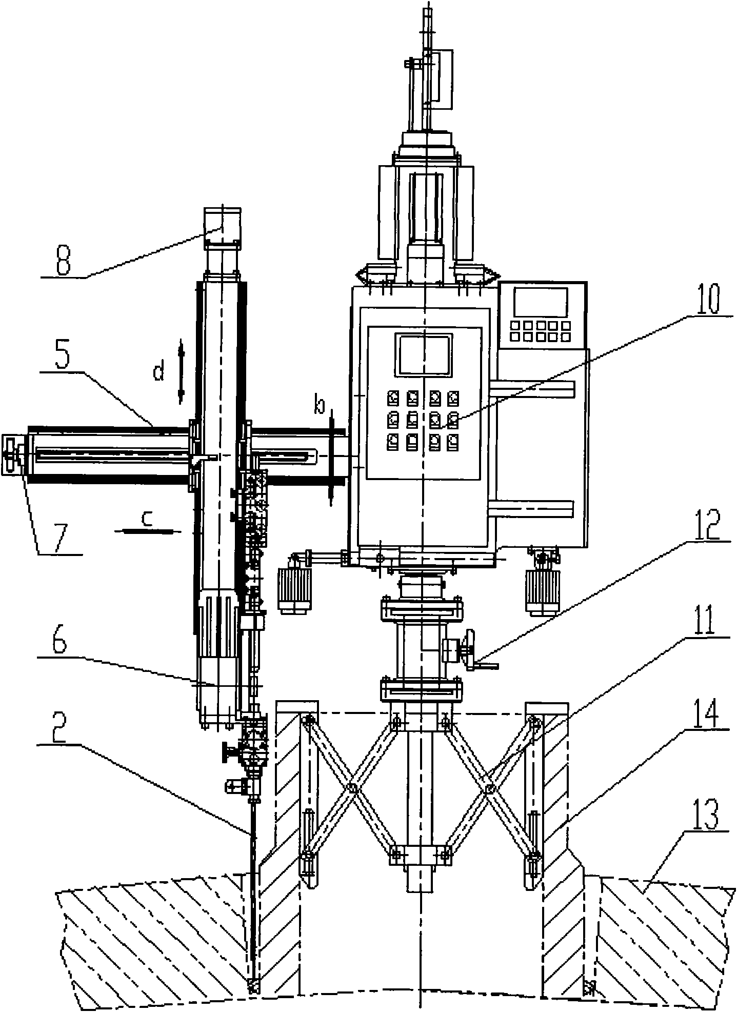
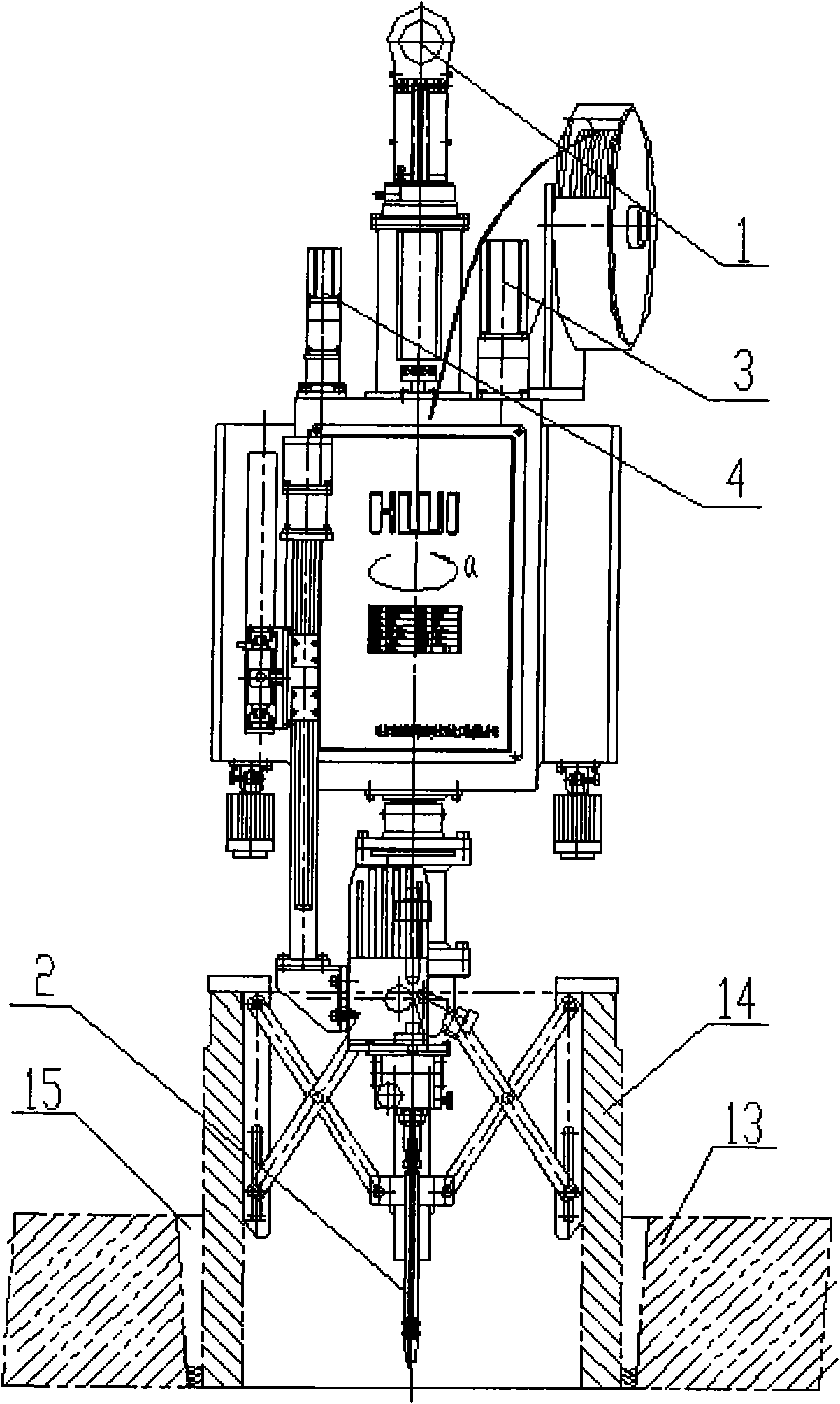
[0052] Lift the whole welding device to the top of the welded pipe 14 and the cylinder 13, the clamping and positioning device 11 falls into the inner hole of the connecting pipe 14, shake and turn the hand wheel 12, the clamping and positioning device 11 clamps the connecting pipe 14 and moves the welding torch 2 The center of rotation is positioned on the center of the socket 14 . Through the man-machine interface on the panel of the device control box 10, input the control parameters such as the diameter d of the welded connecting pipe 14 and the diameter D of the cylinder 13, as well as the welding thickness, number of welding layers, lap joint amount, number of welding passes per layer, etc., and then pass The welding control box inputs welding current, welding voltage and other process parameters to complete the parameter setting link.

[0053] Press the start button on the control panel 10 to start automatic welding. The welding torch head 2-1 is driven by the rotating ...


PUM


Abstract

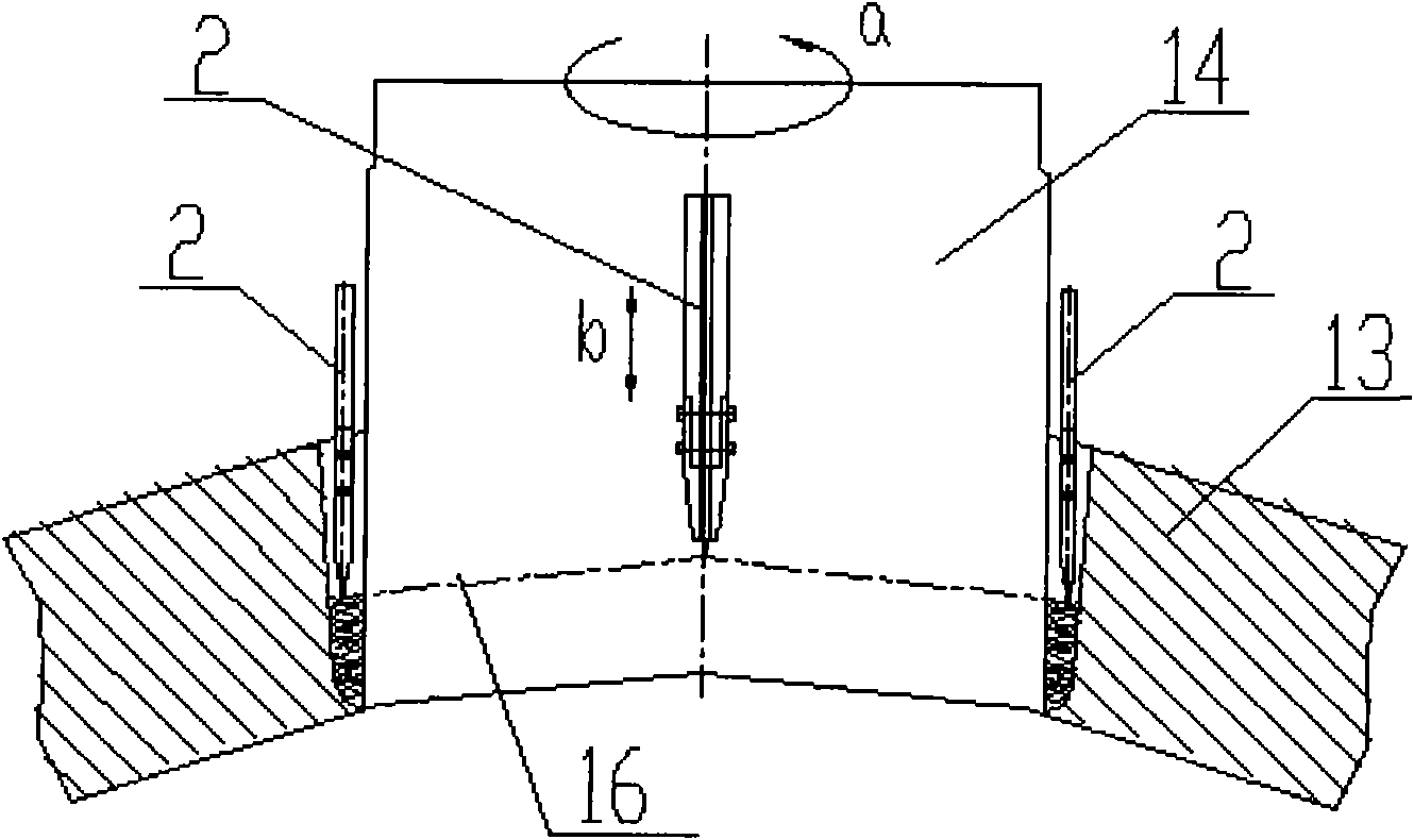
The invention provides a numerical control submerged automatic arc welding device and a numerical control submerged automatic arc welding method for a saddle-shaped narrow bevel and belongs to the technical field of non-planar automatic welding. The invention mainly solves the technical problems of low production efficiency and non-assured welding quality of the welding of heavy pressure vessel in the prior art. The automatic welding device and the automatic welding method of the invention mainly comprise that: a rotating motor (3) rotates to drive a welding gun (2) to perform a rotary motion a; meanwhile, a machine head lifting motor (4) makes a welding gun (2) perform a lifting motion b; the two kinds of motions a and b form a resultant motion through a certain numerical control model; and through the numerical control resultant motion, a welding gun head (2-1) can accurately realize the saddle-shaped path welding of a narrow bevel. Meanwhile, the numerical control of the welding times and welding amount of each layer, the number of the welded layers and the thickness of the welding channels in the narrow bevel can be realized. The device and the method are mainly used in the saddle-shaped welding of the narrow bevel between a connecting pipe and a cylinder in the heavy pressure vessel.

Description

technical field [0001] The numerical control saddle-shaped narrow groove submerged arc automatic welding device and its submerged arc automatic welding method proposed by the present invention belong to the technical field of non-planar space welding connection, and in particular relate to a saddle-shaped narrow groove submerged arc automatic welding device and a submerged arc automatic welding method . Background technique [0002] Heavy-duty pressure vessels mainly include pressure shells in nuclear power units, coal liquefaction reactors in large-scale coal-to-gas complete sets of equipment, hydrogenation reactors in large-scale ethylene plants, and boiler drums in large-scale thermal power generation units. [0003] The cylinder body of a pressure vessel needs to be welded with several or even dozens of mouthpieces. The weld seam is a space saddle-shaped curve, but according to different groove forms, multi-layer and multi-pass continuous welding is required. These weld ...

Claims


Application Information

Patent Timeline
IPC IPC(8): B23K9/18B23K9/235
Inventor 于丹杨克非孟兆林王锴王景洲
Owner HARBIN WELDING INST LTD
Learn More