Setting Controller Termination in a Memory Controller and Memory Device Interface in a Communication Bus

a technology of memory controller and controller, which is applied in the direction of power supply for data processing, instruments, liquid/fluent solid measurement, etc., can solve the problems of timing offset, dram and controller impedance mismatch, and variable final dram training value, etc., to reduce mismatches and improve timing margins. , the effect of reducing mismatches

Inactive Publication Date: 2010-07-29
IBM CORP
View PDF22 Cites 23 Cited by
  • Summary
  • Abstract
  • Description
  • Claims
  • Application Information

AI Technical Summary

Benefits of technology

This patent describes a way to improve the performance of computer memories by reducing errors caused by misaligned data. It does this by measuring and adjusting the resistance levels in the circuit that connects the memory devices to their controllers. By doing this, it helps ensure better synchronization between different parts of the system, resulting in faster processing times for computers and other electronic systems.

Problems solved by technology

The technical problem addressed in this patent text relates to improving the alignment between reference voltage levels and actual data eyes when transmitting signals over various electrical communication buses, caused by differences in processing variables and resolution. These misalignments lead to timeoffs and performance degradation, requiring a solution for reducing these errors while still maintaining optimal signal quality.

Method used


Image

  • Setting Controller Termination in a Memory Controller and Memory Device Interface in a Communication Bus
  • Setting Controller Termination in a Memory Controller and Memory Device Interface in a Communication Bus
  • Setting Controller Termination in a Memory Controller and Memory Device Interface in a Communication Bus

Examples


Embodiment Construction

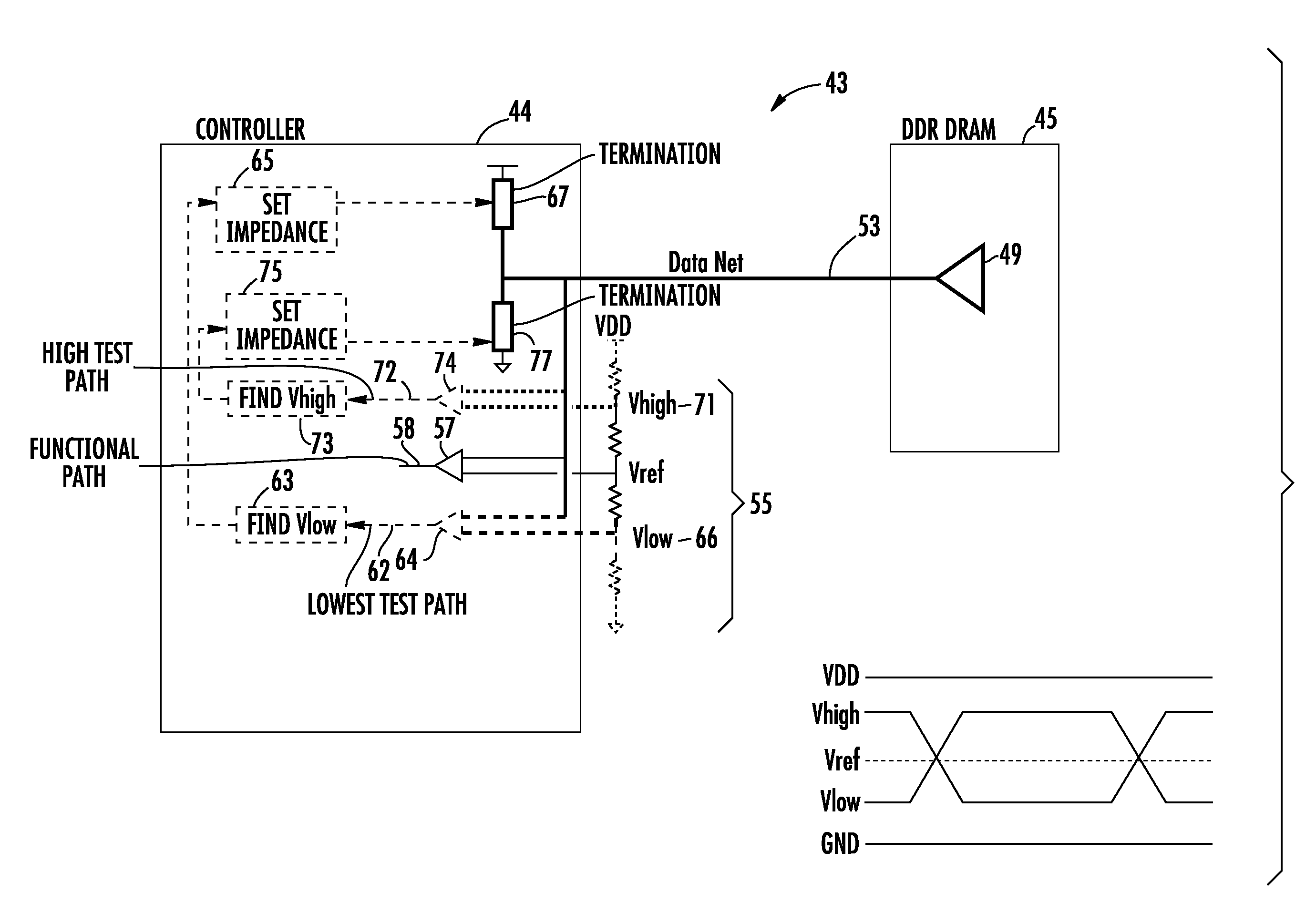
[0019]Embodiments consistent with the invention may capitalize on the ability to couple a memory device such as a DRAM and a memory controller during driver training to reduce mismatches by adjusting the impedance at a termination device of the memory controller to yield improvements in timing margins. In more general terms, coupling the components on a shared electrical bus through level adjustment dramatically removes known offset issues. While embodiments of the invention are described specifically for a GDDR3 interface from a memory controller to a GDDR3 memory device, the system and method may be applied to any number of system and sub-system electrical communication buses.

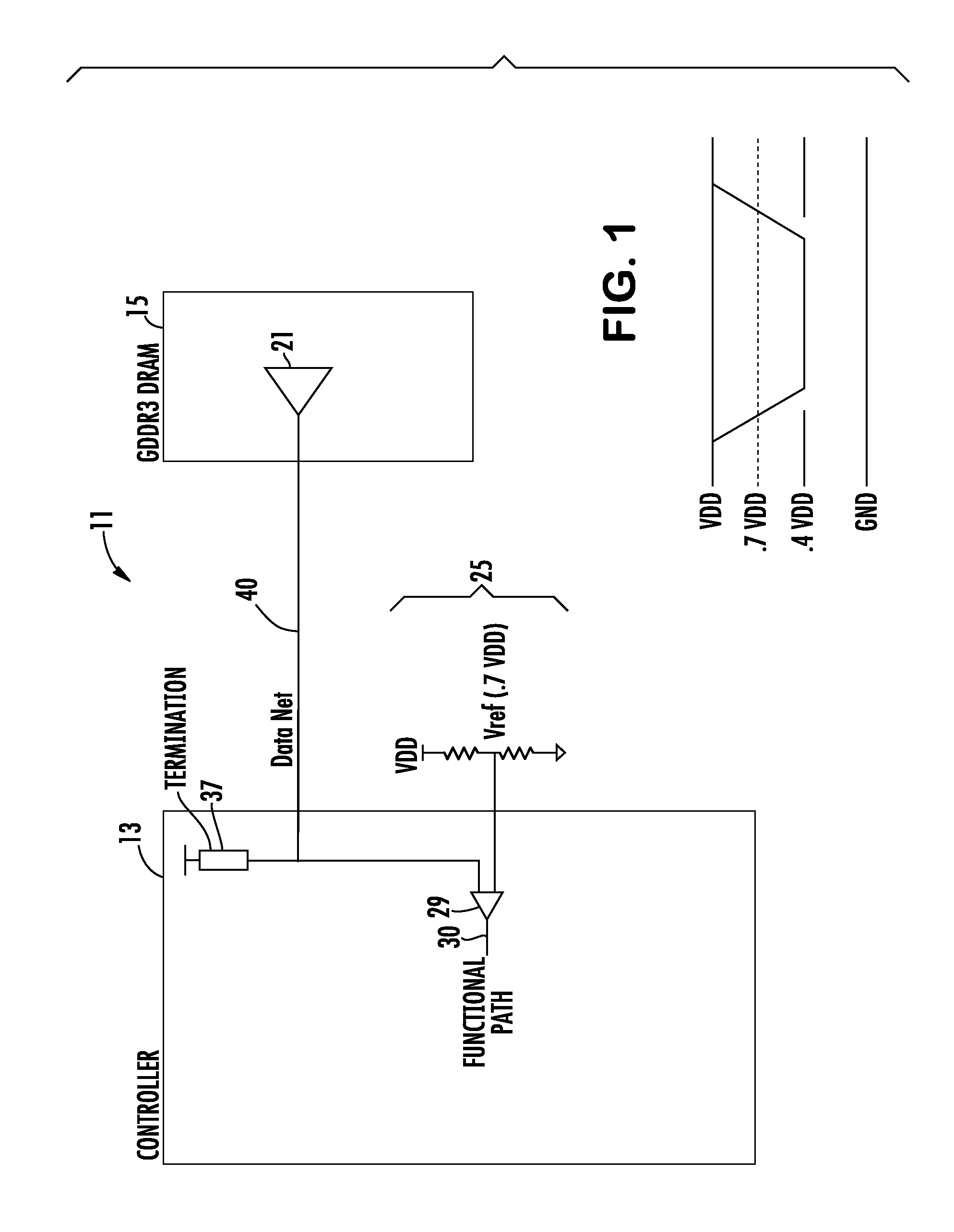
[0020]Turning more particularly to the drawings, FIG. 1 shows a typical GDDR3 interface system 11. More particularly, a memory controller 13 is connected through a data net 40 to a GDDR3 DRAM 15. The data net 40, i.e., a bus connection, connects to a functional path 30 including a comparator 29 in the memory ...


PUM


Abstract

A DRAM and memory controller are coupled during driver training to reduce mismatches. The impedances of the system are controlled through a termination at the controller to yield improvements in timing margins. The coupling of the components on a shared electrical bus through adjustment of the termination values during training removes known offset issues.

Description


Claims


Application Information

Patent Timeline
Owner IBM CORP
Why Eureka
Try Eureka