Modular steel bridge

a technology of modular steel bridges and steel bridges, applied in bridge construction, bridge structural details, construction, etc., can solve the problems of increasing the amount of non-destructive inspection, difficult to improve defect parts, and long time for a plurality of bolts to engage at the construction site, so as to prevent fatigue failure and facilitate partial repair

Inactive Publication Date: 2010-08-05
RES INST OF IND SCI & TECH
View PDF12 Cites 5 Cited by
  • Summary
  • Abstract
  • Description
  • Claims
  • Application Information

AI Technical Summary

Benefits of technology

[0018]The present invention has been made in an effort to provide a modular steel bridge having advantages of preventing fatigue failure that occurs at a welded part of the girder segment and the hinge structure, and allowing easy partial repair of a hinge structure in which a crack is generated.

Problems solved by technology

However, the on-the-spot welding has a large generation frequency of defects, it is difficult to improve defect parts, and it may greatly Influence temporary precision because of shrinkage of the welded structure.
Also, it has a drawback of increasing the amount of nondestructive inspection because of the reliability of the on-the-spot welding.
However, it takes much time to engage a plurality of bolts at the construction site, and the introduced axial force of the bolt is greatly changed by the engagement method and engagement order.
However, as the hinge structure of the modular steel bridge having the above-noted connection specification structure is connected to the connection part of the girder segment through welding, fatigue failure can be easily generated at the welded part by repeated loads during use of the girder.
Also, when a crack occurs in the hinge structure, it is impossible to repair the cracked part and reconstruction of the entire girder is needed.
In addition, the modular steel bridge having the above-noted connection specification has a problem of manufacturing the hinge structure by using an ultra-thick plate with a thickness of greater than 100 mm so as to resist the tensile force applied to the hinge structure.
It is difficult to buy the ultra thick plates from domestic shops in Korea, but it is possible to manufacture the hinge structure through casting and forging as a substitute for the ultra thick plate, which however is not a desirable solution since the production cost is substantially increased.
Further, the modular steel bridge having the conventional hinge-structured connection specification has a less stable structure, and hence, when the hinge structure generates a crack as a result of repeated loads, the girder structure may dramatically fail.

Method used


Image

  • Modular steel bridge
  • Modular steel bridge
  • Modular steel bridge

Examples


Embodiment Construction

[0056]The present invention will be described more fully hereinafter with reference to the accompanying drawings, in which exemplary embodiments of the invention are shown. As those skilled in the art would realize, the described embodiments may be modified in various different ways, all without departing from the spirit or scope of the present invention.

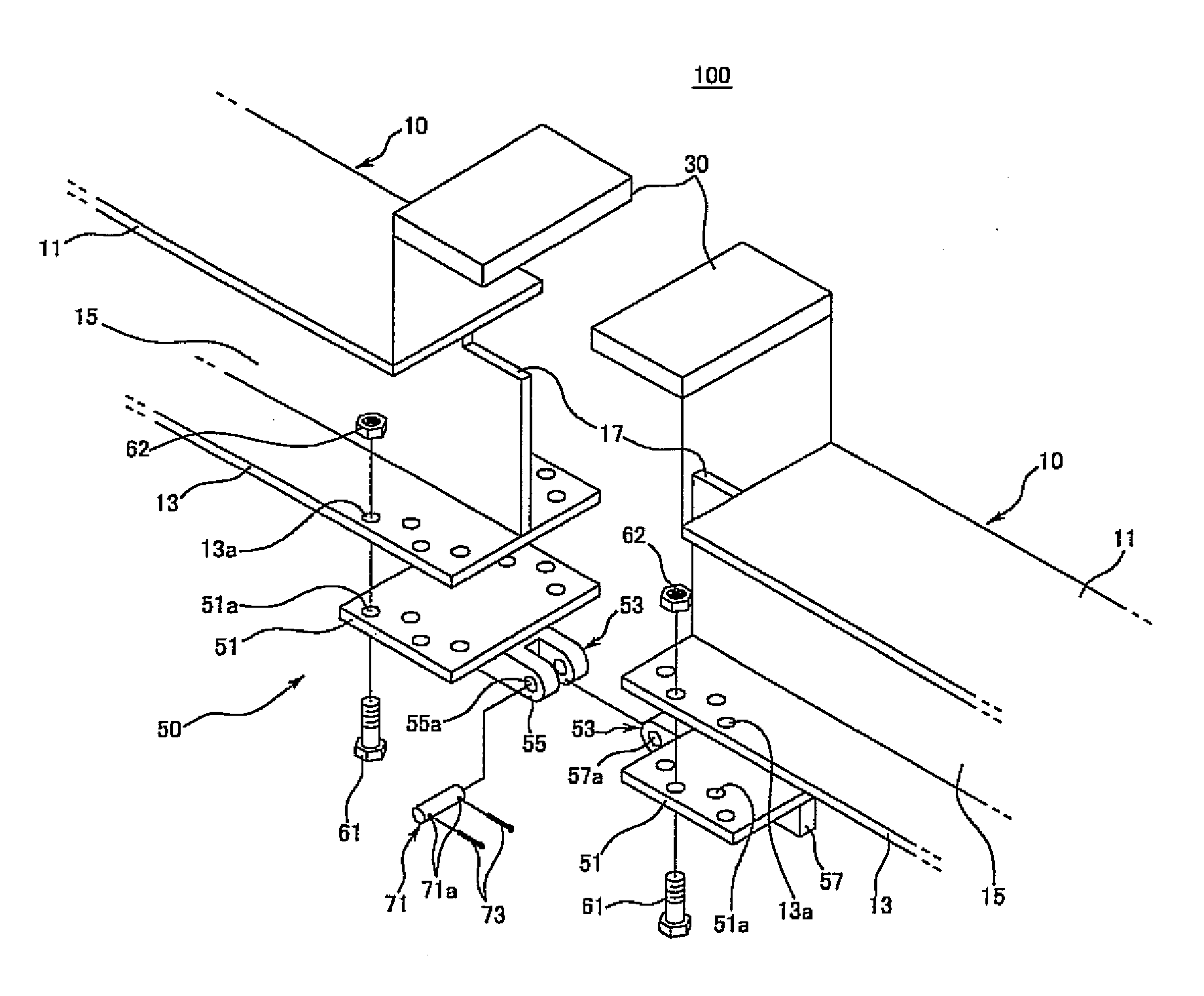
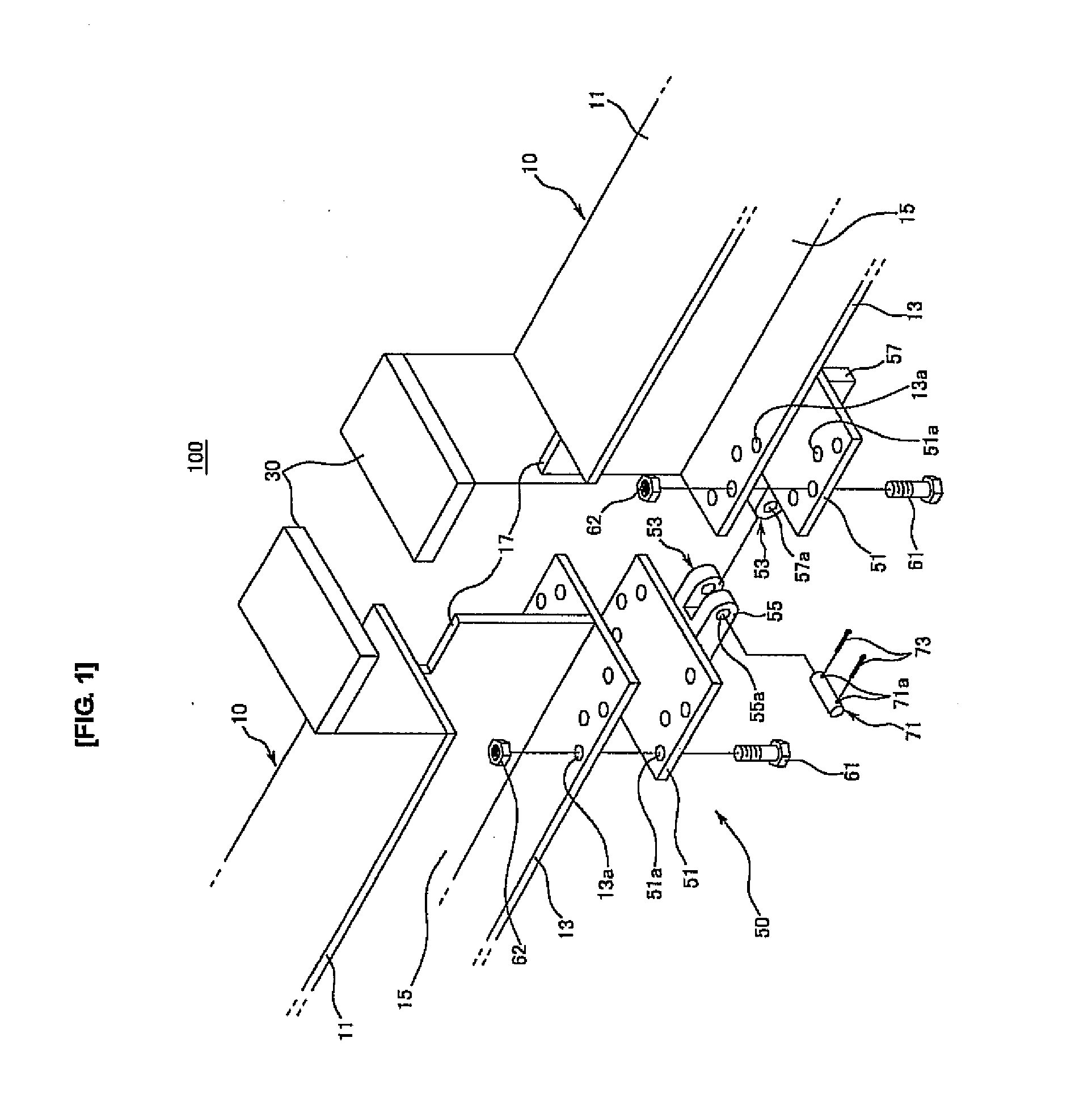
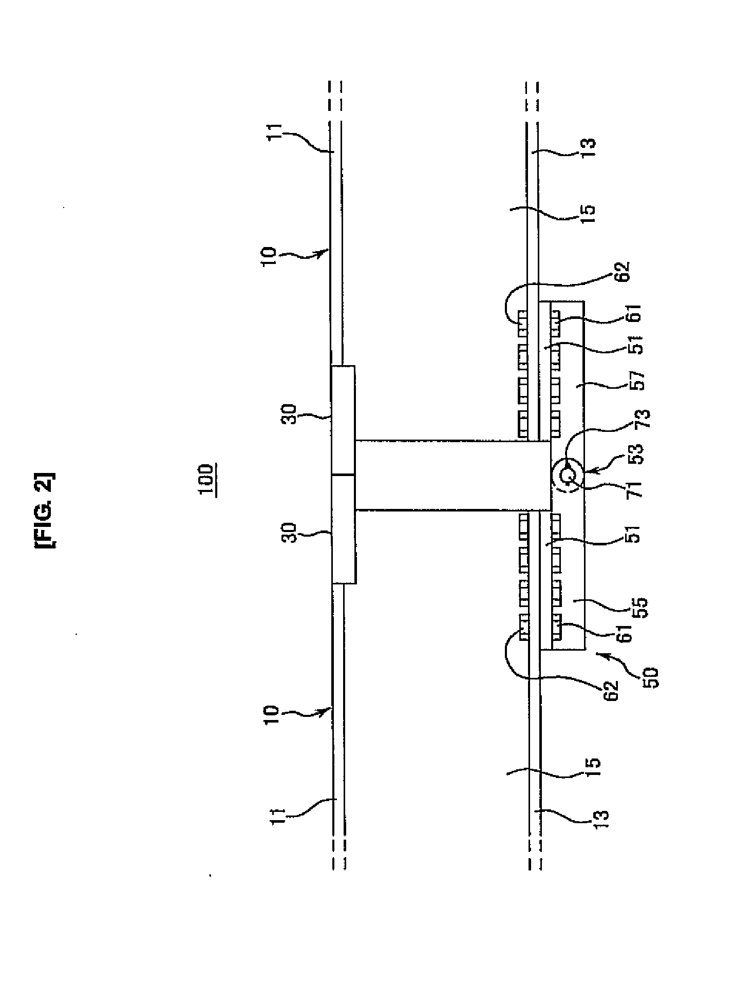
[0057]FIG. 1 is an analyzed perspective view for a modular steel bridge according to a first exemplary embodiment of the present invention, and FIG. 2 is a front schematic diagram of FIG. 1.

[0058]Referring to the drawings, the modular steel bridge 100 is a temporary bridge in the simple bridge or continuous bridge format, and has a structure in which at least two steel girder segments 10 are connected with each other.

[0059]The steel girder segments 10 are manufactured in a factory in advance, are delivered to the construction site, and are then connected.

[0060]Here, each steel girder segment 10 includes an upper flange 11, a lower f...


PUM


Abstract

A modular steel bridge is configured by combining at least two steel girder segments, and it includes a bearing block installed to be connected to an upper flange of a connection end of each steel girder segment and a web, and a hinge assembly installed to be attachable to the lower flange of each connection end and hinge-connecting the connection ends.

Description

BACKGROUND OF THE INVENTION[0001](a) Field of the Invention[0002]The present invention relates to a modular steel bridge. More particularly, the present invention relates to a modular steel bridge that is generated by connecting steel girder segments in a hinge format.[0003](b) Description of the Related Art[0004]In general, a modular steel bridge is a temporary bridge in the simple bridge or continuous bridge format, and it has a structure in which at least two steel girder segments are connected as a single body.[0005]The steel girders are generally manufactured as segments so as to increase the conveyance limit and increase installation convenience, and the segments are generally connected by welds or bolts at the construction site.[0006]Regarding constructing the modular steel bridge, connection of girder segments by welding improves appearance of the entire structure compared to connection by bolts, and simultaneously reduces the overall steel amount since it requires no splice...

Claims


Application Information

Patent Timeline
Patent Type & Authority Applications(United States)
IPC IPC(8): E01D1/00E01D2/00E01D2/02E01D2/04
CPCE01D15/133E01D2101/30E01D19/04
Inventor LEE, DAE-YONGKIM, JIN-KOOKCHOI, BYUNG-HOPARK, CHAN-HEEHWANG, MIN-OHYOON, TAE-YANG
Owner RES INST OF IND SCI & TECH
Why Eureka
Try Eureka