Ceiling-embedded air conditioner

a ceiling-embedded, air-conditioning technology, applied in the field of ceiling-embedded air-conditioning, can solve the problems of high manufacturing cost, complex structure of the air passage, etc., and achieve the effect of simple structure and prevention of condensation

Inactive Publication Date: 2010-08-05
TOSHIBA CARRIER CORP
View PDF12 Cites 72 Cited by
  • Summary
  • Abstract
  • Description
  • Claims
  • Application Information

AI Technical Summary

Benefits of technology

[0015]The present invention has been made in consideration of the above circumstances, and an object of the invention is to provide a ceiling-embedded air conditioner which enables the air subjected to the air exchange to be blown into a room in every direction desired, without having to add a blow-out port and a louver to the corner portions of a decorative panel, and which prevents condensation at the end portions of the louver with a simple structure.

Problems solved by technology

Hence, the air conditioner is disadvantageous in that it is complex in structure and requires a high manufacturing cost.
On the other hand, the air conditioner disclosed in Jpn. Pat. Appln. KOKAI Publication No. 8-94160 has problems in that the structure of the air passage is complex.
Since the number of parts required is therefore large, the manufacturing cost is inevitably high.

Method used


Image

  • Ceiling-embedded air conditioner
  • Ceiling-embedded air conditioner
  • Ceiling-embedded air conditioner

Examples


first embodiment

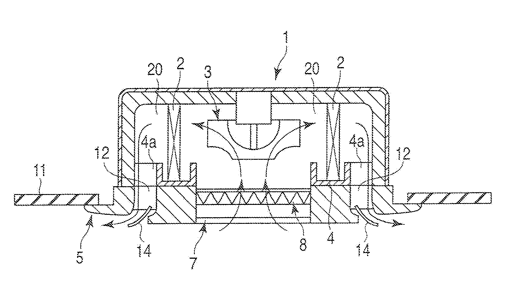
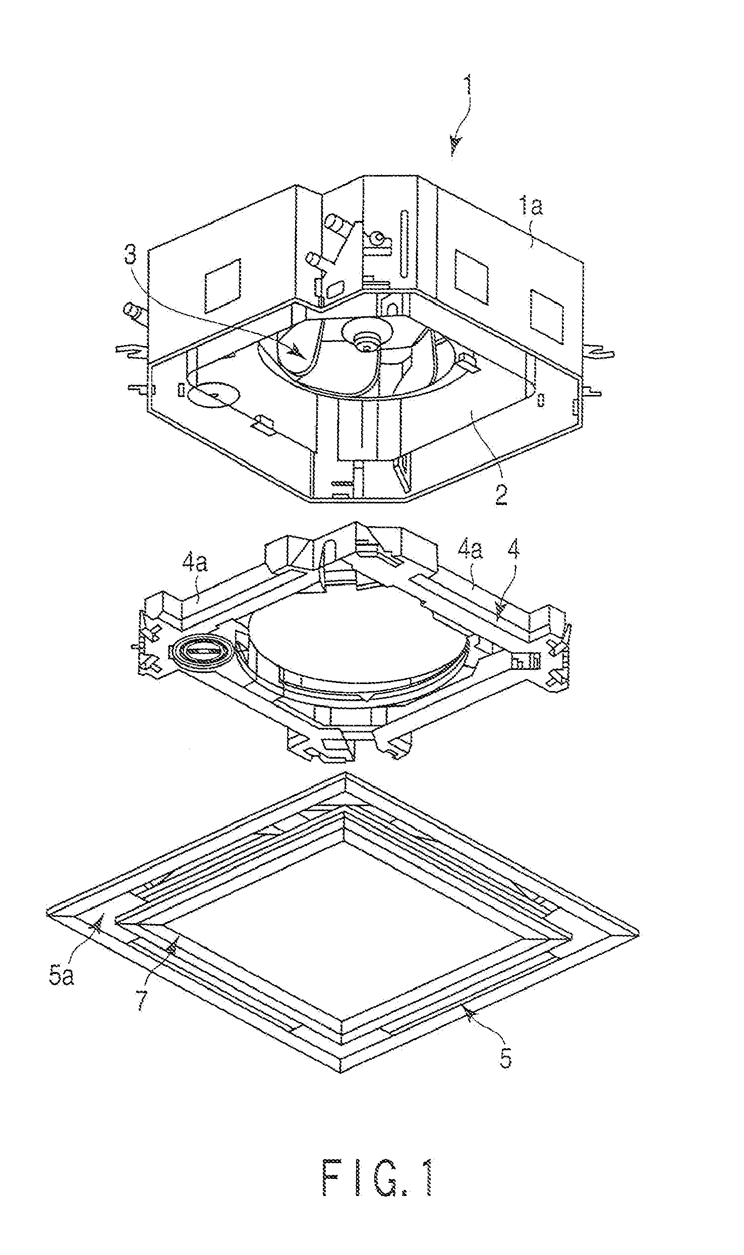
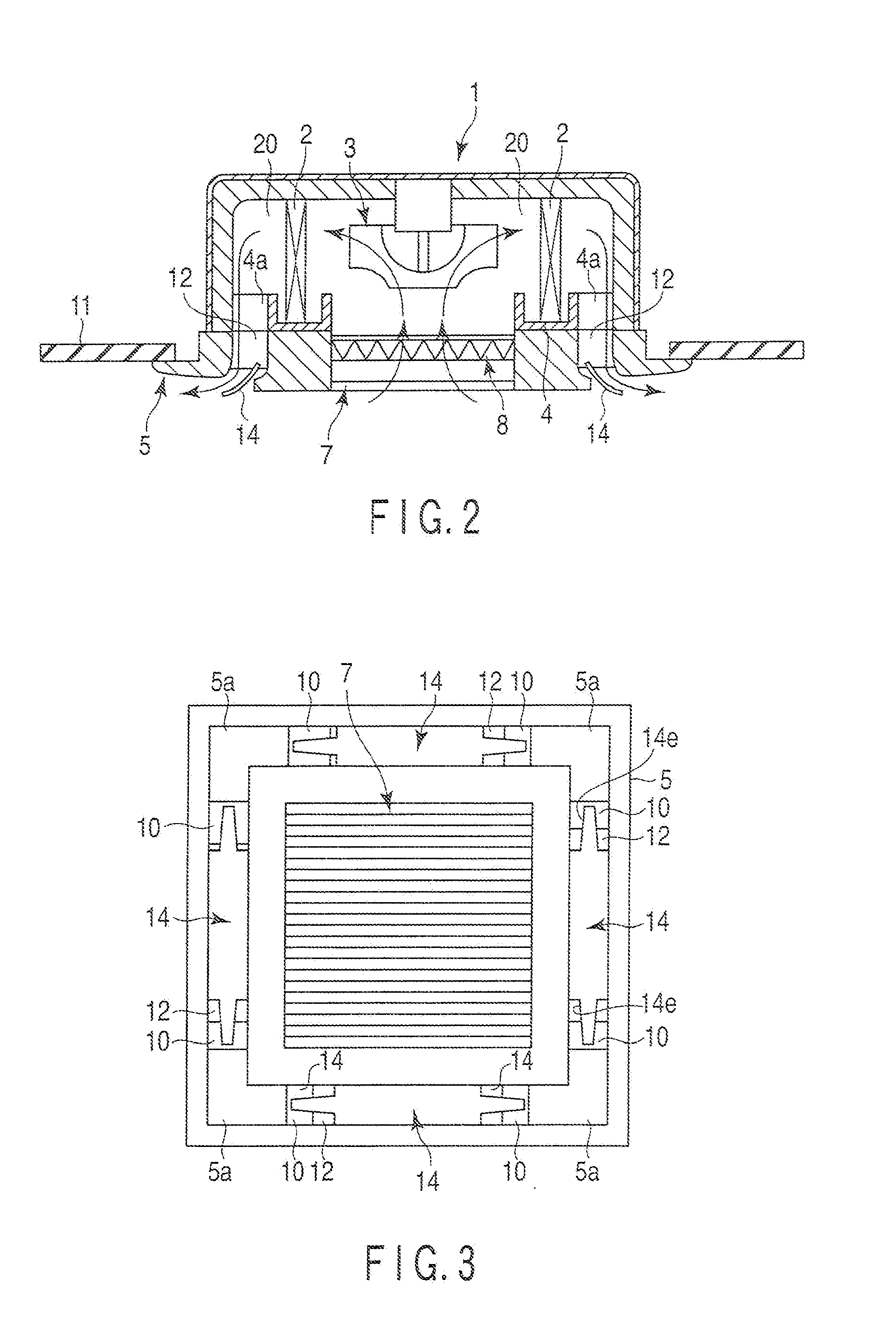
[0038]FIG. 1 is an exploded perspective view of an indoor unit 1 of a ceiling-embedded air conditioner according to one embodiment of the present invention. FIG. 2 shows a state in which the indoor unit 1 is provided in a ceiling 11.

[0039]The indoor unit 1 comprises a casing 1a. A turbo fan 3, serving as an air blower, is provided substantially in the center of the casing 1a. An indoor heat exchange unit 2 surrounds the outer periphery of the turbo fan 3. A drain pan 4 is provided on the lower side of the indoor heat exchange unit 2. A drain pan dent section 4a is formed in each outer side wall of the drain pan. The drain pan dent section 4a communicates with a blow-out port 12 provided in a decorative panel 5 (to be described later) and constitutes part of an air passage 20.

[0040]A decorative panel 5 is provided on the lower side of the casing 1a. A suction grille 7, serving as a suction port, is located substantially in the center of the decorative panel in such a manner that the ...

second embodiment

[0052]FIG. 11 shows the second embodiment of the present invention.

[0053]In the first embodiment described above, the width of the louver 14 gradually decreases, from the central portion 14a to the longitudinal ends 14b. In the second embodiment, the width of a blow-out port 21 increases from the central portion to the longitudinal ends. A louver 22 having a constant width in the longitudinal direction thereof is arranged in the blow-out port 21. A wind-shielding plate 23 configured to prevent the flow-out air from falling down is provided at each end of the blow-out port 21.

[0054]In the second embodiment, when the louver 14 is rotated and kept in the horizontal state (at an angle corresponding to a slightly closed state), the amount of wind coming from the central portion of the blow-out port 21 is decreased, and the amount of wind coming from the end portions is increased. In this manner, the air can be guided laterally and blown out from the end portions of the louver 14, and the...

third embodiment

[0057]FIGS. 13-16 show the third embodiment of the present invention.

[0058]FIG. 13 is a perspective view showing part of a drain pan 4, and FIG. 14 is a sectional view of a side portion of the drain pan 4.

[0059]A pair of projections 25, which are projected upward, are formed on the upper surface of a side wall of the drain pan 4, with a predetermined distance kept away from each other. The paired projections 25 are located in the upper region of the end portions of a blow-out port 12. The upper surface and the inner wall surface of the drain pan 5 are coated with resin 13, and the projections 25 are integrally formed of resin 13.

[0060]Part of the air that has been subjected to heat exchange by the heat exchange unit 2 rises along the inner wall surface of the drain pan 4, as shown in FIG. 14. When the rising air reaches the upper surface of the side wall of the drain pan 4, the air in the center flows in a horizontal direction and enters a drain pan dent section 4a, as indicated by ...


PUM


Abstract

An air passage has a blow-out side opening opposed to a position other than the longitudinal ends of a blow-out port of a decorative panel. The width of a louver, as determined in an air-blowing direction, decreases from a longitudinal center of the louver to the ends of the louver.

Description

CROSS REFERENCE TO RELATED APPLICATIONS[0001]This is a Continuation Application of PCT Application No. PCT / JP2008 / 068819, filed Oct. 17, 2008, which was published under PCT Article 21(2) in Japanese.[0002]This application is based upon and claims the benefit of priority from prior Japanese Patent Applications No. 2007-278133, filed Oct. 25, 2007; and No. 2007-278134, filed Oct. 25, 2007, the entire contents of both of which are incorporated herein by reference.BACKGROUND OF THE INVENTION[0003]1. Field of the Invention[0004]The present invention relates to a ceiling-embedded air conditioner which regulates the blown-out air stream in such a manner as to uniformly air-condition the entire room, and which prevents condensation on the louver.[0005]2. Description of the Related Art[0006]This type of air conditioner comprises an air blower and a heat exchange unit provided in the unit casing. The rotation of the air blower causes the indoor air to be sucked from a suction port. The sucked...

Claims


Application Information

Patent Timeline
Patent Type & Authority Applications(United States)
IPC IPC(8): F25D21/14F24F7/00F24F13/14
CPCF24F2001/0037F24F1/0014F24F2013/0616F24F13/14F24F1/0047F24F2221/14
Inventor YAMAGUCHI, KIYOSHINAKANO, HIDEKAZUMUKAI, TAKAHIKO
Owner TOSHIBA CARRIER CORP
Why Eureka
Try Eureka