Optical fiber electric current measurement apparatus and electric current measurement method

Inactive Publication Date: 2010-08-05
THE TOKYO ELECTRIC POWER CO INC
View PDF4 Cites 14 Cited by
  • Summary
  • Abstract
  • Description
  • Claims
  • Application Information

AI Technical Summary

Benefits of technology

[0073]According to the present invention, in the optical fiber electric current measurement apparatus which detects the electric current by measuring the magnitude of the Faraday effect applied when the linearly-polarized light passing through the polarization splitter or the optical polarizer is inci

Problems solved by technology

However, this type of sensor is complicated in structure.
On the other hand, it is disadvantageous in that a large number of optical elements are required, and a circuit configuration or setup becomes complicated because it is necessary to adjust principal axis directions of mutual positions of these optical elements.
(ii) In both transmission and reflection types of optical fiber electric current measurement apparatuses, errors may be generated in the measurement

Method used


Image

  • Optical fiber electric current measurement apparatus and electric current measurement method
  • Optical fiber electric current measurement apparatus and electric current measurement method
  • Optical fiber electric current measurement apparatus and electric current measurement method

Examples


Embodiment Construction

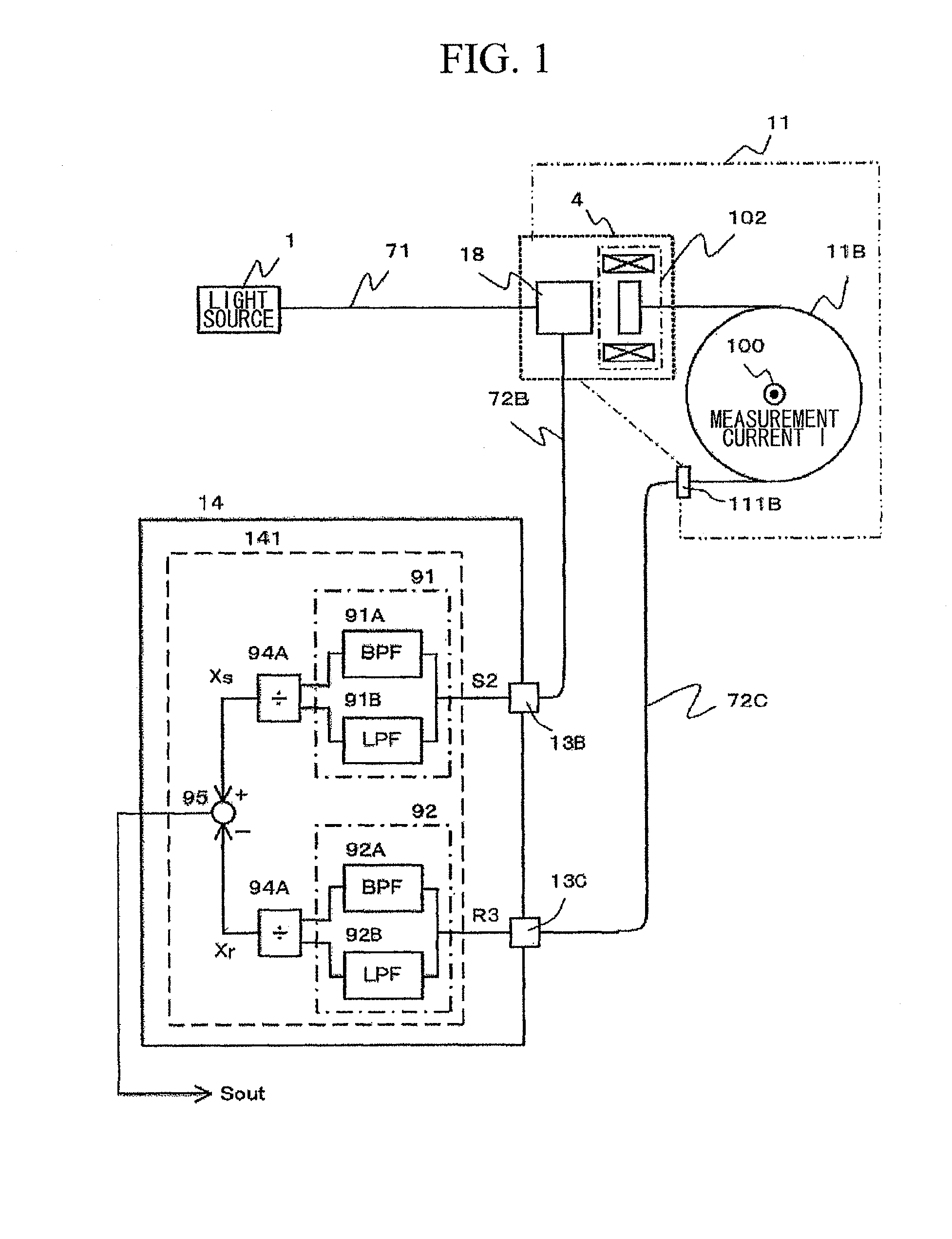
[0100]FIG. 1 illustrates an exemplary configuration according to an embodiment of the present invention, in which an electric current measurement apparatus using a reflection type optical current sensor device characterized in that a part of light output from a light source and transmitted through a polarization splitter is separated in an optical reference signal extractor provided between the polarization splitter and a reflector and is used as an optical reference signal.

[0101]Referring to FIG. 1, an optical fiber electric current measurement apparatus according to an embodiment of the present invention includes a optical transmission fiber 71, signal transmission fiber 72B and 72C, an optical element 4 having a polarization splitter 18 and a Faraday rotor 102, and sensor fiber 11B. It is noted that the Faraday rotor 102 and the polarization splitter 18 are formed in an integrated structure optically connected as shown in FIG. 4. In addition, the Faraday rotor 102 and the polariz...


PUM


Abstract

In a reflection type optical fiber electric current measurement apparatus, a standardization reference signal (Xr), which is defined by the intensity (Pr) of the optical reference signal transmitted through a partial transmission mirror by using a reflector (111B) provided in one end of a sensor fiber as the partial transmission mirror, is subtracted from a standardization detection signal (Xs), which is defined by the intensity (Ps) of the optical detection signal obtained from the light reflected at the partial transmission mirror. Thereby, it is possible to remove noise caused by fluctuation in the polarization state (B) as well as fluctuation in the luminescence intensity (A) of the light source.

Description

TECHNICAL FIELD[0001]The present invention relates to an electric current measurement method and an electric current measurement apparatus using an optical fiber.[0002]Priority is claimed on Japanese Patent Application No. 2007-234542, filed on Sep. 10, 2007, the contents of which are incorporated herein by reference.BACKGROUND ART[0003]Apparatuses using optical sensors are being focused on as electric current or voltage measurement apparatuses. An example of an optical sensor includes a high accuracy sensor such as a so-called optical heterodyne type sensor which uses a photoelectric detector to receive and detect interference generated by mixing an optical signal modulated by a measurement target with a local oscillation signal having a frequency different from the optical signal. (e.g., refer to Non-patent Document 1).[0004]However, this type of sensor is complicated in structure. For this reason, recently, a method or apparatus of detecting an electric current or voltage by conv...

Claims


Application Information

Patent Timeline
IPC IPC(8): G01R15/24G01R19/00
CPCG01R15/246
Inventor KUROSAWA, KIYOSHI
Owner THE TOKYO ELECTRIC POWER CO INC
Why Eureka
Try Eureka