Creepage circuit breaker

A leakage circuit breaker and circuit technology, which is applied in the direction of circuit devices, emergency protection circuit devices, electrical components, etc., can solve the problems of insufficient Is level of the output circuit and hinder the normal operation of the leakage test function, and achieve easy design, reliability, and large size Amplification level, the effect of expanding the passband width

Active Publication Date: 2009-10-07
FUJI ELECTRIC FA COMPONENTS & SYST CO LTD
View PDF5 Cites 2 Cited by
  • Summary
  • Abstract
  • Description
  • Claims
  • Application Information

AI Technical Summary

Problems solved by technology

This problem is that the magnitude of the output circuit Is fed from the secondary side of the zero-phase current transformer 3 to the leakage detection circuit 4 is insufficient (too small) to be smaller than the threshold value set by the leakage detection circuit 4, which hinders the normal function of the leakage test operate

Method used


Image

  • Creepage circuit breaker
  • Creepage circuit breaker
  • Creepage circuit breaker

Examples


no. 1 example

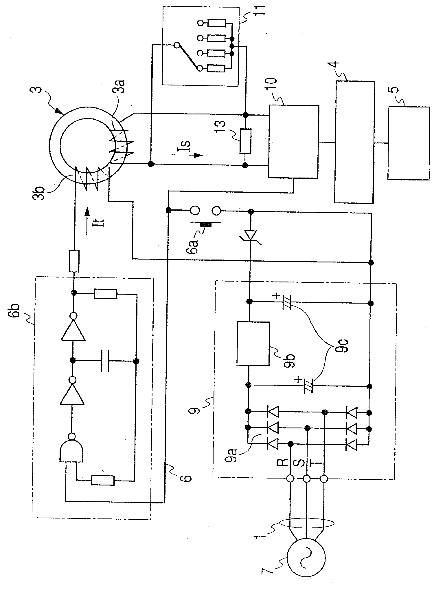
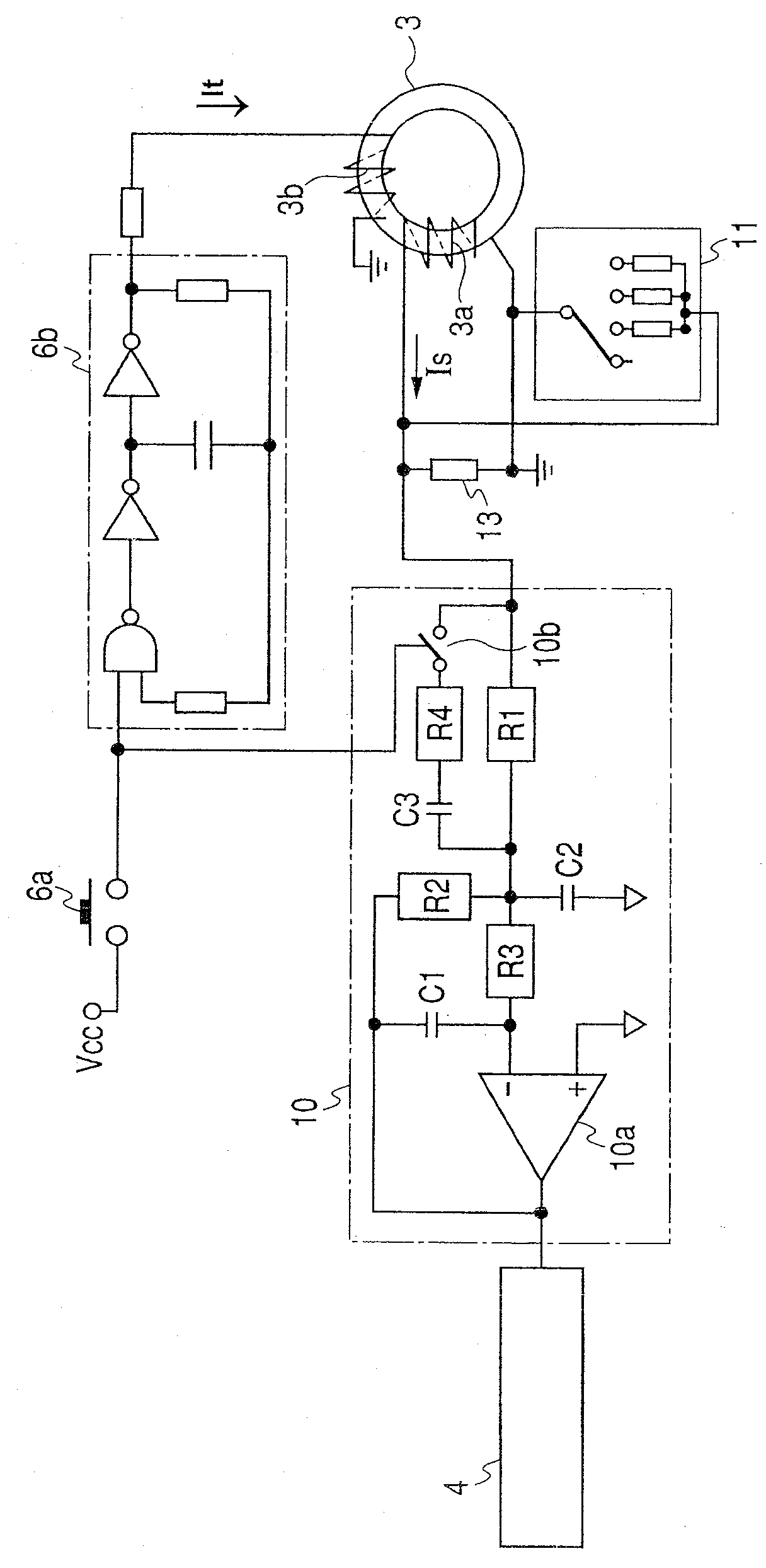
[0057] figure 1 and figure 2 A first embodiment of the invention is shown. figure 1 is a circuit diagram showing the main circuit configuration of the earth leakage circuit breaker according to the first embodiment of the present invention. figure 2 is shown included in the figure 1 Detailed circuit diagram of the active filtering circuit in the filtering and amplifying unit shown. To simplify the drawings, the Figure 7 The input resistors shown adjust the amplification level.

[0058] exist figure 2 In the circuit of the filtering and amplifying unit 10 having the operational amplifier 10a as an amplifying element, a multi-loop feedback type low-pass filter is formed. In this multi-loop feedback type low-pass filter, resistors R1 to R3 and capacitors C1 and C2 are added to the outside of the operational amplifier 10a as low-pass filter elements. Besides, on the side of the inverting input terminal of the operational amplifier 10a, a resistor R4, a capacitor C3, ...

no. 2 example

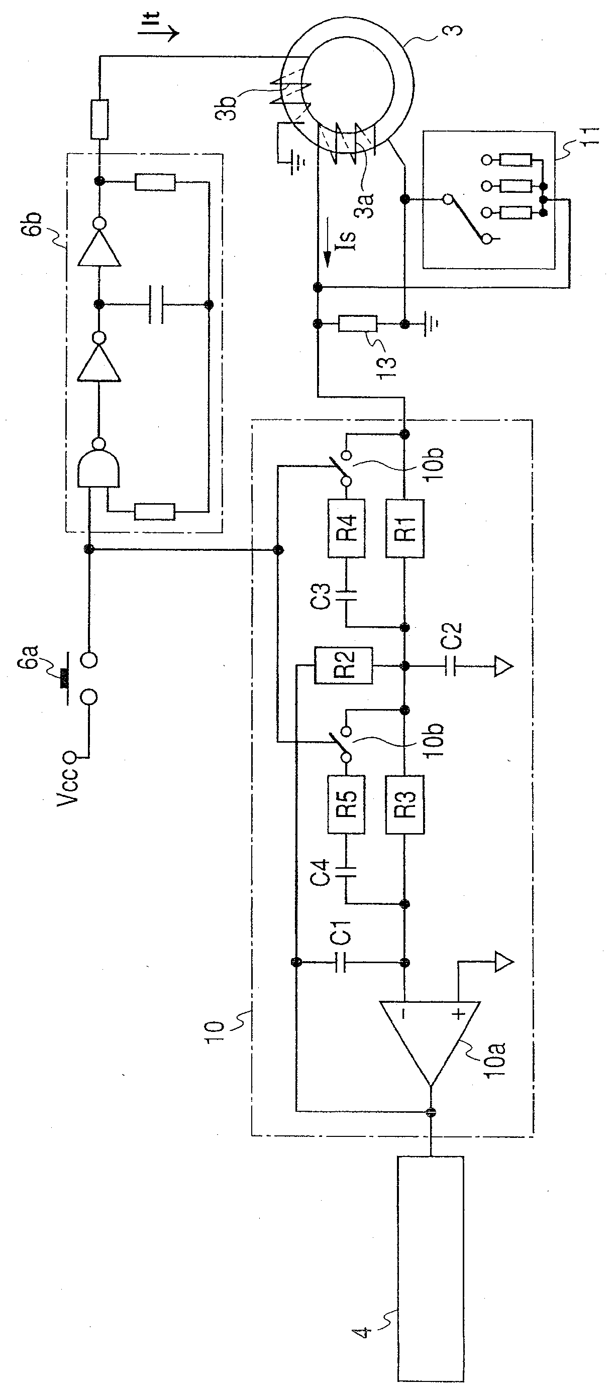
[0065] image 3 A detailed diagram of the active filtering circuit included in the filtering and amplifying unit according to the second embodiment of the present invention is shown in . This embodiment corresponds to requirement 3. In this embodiment, the circuit of the aforementioned first embodiment is further improved to enhance the product reliability of the earth leakage circuit breaker. In the improved circuit, the passband width of the band-pass filter is expanded to prevent the allowable value of the test frequency variation from being smaller than the target value, the above-mentioned variation being caused by the characteristic variation of the circuit element or the temperature variation. image 3 Two combinations are provided in the circuit configuration shown, each combination includes bandpass filter elements and as figure 2 Shown is the analog switch connecting the band-pass filter element and the low-pass filter element during the test. As described below,...


PUM


Abstract

The leakage circuit breaker includes: a zero-phase current transformer (3), which detects the leakage current of the multi-phase AC circuit (1); a leakage detection circuit (4); Open the contact of the AC circuit (1); the test circuit (6) feeds the test current (It) of the simulated leakage through the conduction test switch (6a); the filtering and amplification unit (10) is arranged on the zero-phase current transformer (3 ) and the leakage detection circuit (4), including an operational amplifier (10a) as an amplifying element to amplify the secondary side output of the zero-phase current transformer (3) at an amplification level corresponding to the setting value of the sensitivity setting unit (11) Current (Is). In the earth leakage circuit breaker, an active filter circuit including an operational amplifier (10a) is contained in a filter and amplifying unit (10). During the test, the active filter circuit is switched from a low-pass filter circuit to a band-pass circuit to remove noise and offset components that cause test failures.

Description

technical field [0001] The present invention relates to a leakage circuit breaker used to detect leakage in a power distribution system, so as to prevent leakage accidents before they occur, in particular to a leakage circuit breaker provided with a test circuit for determining the function of leakage tripping. Background technique [0002] It is well known that an earth leakage circuit breaker is provided with a test circuit for confirming the operation of the earth leakage tripping function (see Patent Document 1, for example). Figure 4 is a block diagram of the circuit disclosed in Patent Document 1, which shows an example circuit of the relevant earth leakage circuit breaker provided with the test circuit. [0003] exist Figure 4 In, reference numerals 1, 2 and 3 respectively denote a three-phase alternating current (AC) circuit, a main circuit switch contact device for switching the AC circuit 1, and detecting a leakage current in the AC circuit 1 by using the AC circu...

Claims


Application Information

Patent Timeline
Patent Type & Authority Patents(China)
IPC IPC(8): H01H83/14H01H83/04
CPCH02H3/335A61F2/04A61F2/14A61F2/148
Inventor 工藤高裕佐佐木昭治高桥康弘
Owner FUJI ELECTRIC FA COMPONENTS & SYST CO LTD
Why Eureka
Try Eureka