Optical transmission system

a transmission system and optical transmission technology, applied in the direction of fibre transmission, distortion/dispersion elimination, electrical equipment, etc., can solve the problems of high construction cost of optical transmission system, difficult to apply conventional optical transmission system to commercial systems, etc., and achieve high-quality output electrical signals. , the effect of reducing construction cos

Inactive Publication Date: 2006-03-02
PANASONIC CORP
View PDF8 Cites 3 Cited by
  • Summary
  • Abstract
  • Description
  • Claims
  • Application Information

AI Technical Summary

Benefits of technology

[0011] According to the stated construction, the optical receiver of the optical transmission system can intensity-modulate the received optical signal, generate two optical signals of which the intensity-modulated components are in antiphase with each other, convert the generated two optical signals into electrical signals respectively, and generate the output electrical signal. Accordingly, the optical receiver does not need to receive two optical signals of which the intensity-modulated components are in antiphase with each other, which is different from the conventional optical transmission system. In other wor...

Problems solved by technology

This is a cause of the high cost for constructing an optical transmission system.
Therefore, i...

Method used


Image

  • Optical transmission system
  • Optical transmission system
  • Optical transmission system

Examples


first embodiment

1. The First Embodiment

[0021] The following is a description of an optical transmission system 1 according to the first embodiment of the present invention.

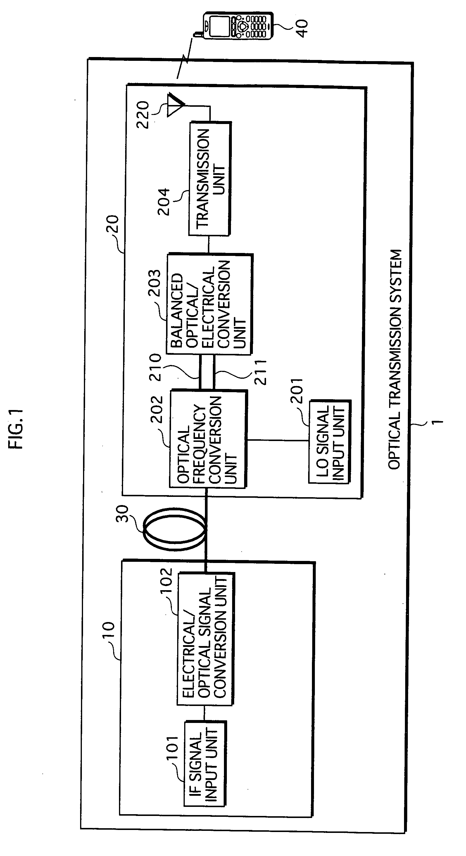
[0022] As FIG. 1 shows, the optical transmission system 1 includes an optical transmitter 10, an optical receiver 20, and an optical fiber 30. The optical transmitter 10 and the optical receiver 20 are connected to each other by the optical fiber 30.

[0023] The optical transmitter 10 converts an intermediate frequency signal (hereinafter called the “IF signal”) into an optical signal, and transmits the optical signal to the optical receiver 20 via the optical fiber 30. The optical receiver 20 receives the optical signal from the optical transmitter 10 via the optical fiber 30, and converts the IF signal into an RF signal with use of the received optical signal. Then, the optical receiver 20 transmits the RF signal to a mobile telephone 40. The IF signal is an electrical signal having a frequency which is different from that of t...

second embodiment

2. The Second Embodiment

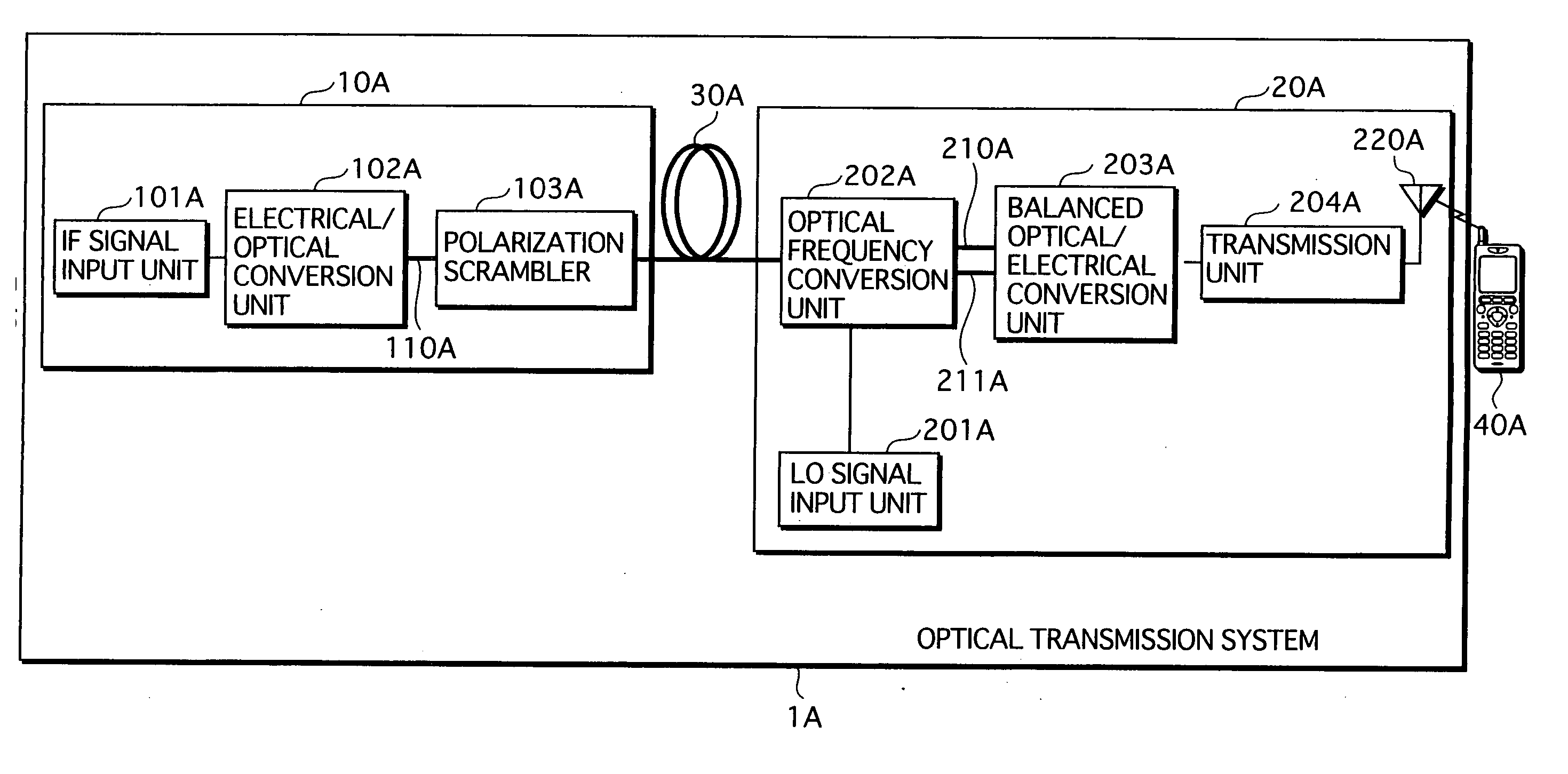
[0061] The following is a description of an optical transmission system 1A according to the second embodiment of the present invention.

[0062] As FIG. 5 shows, the optical transmission system 1A includes an optical transmitter 10A, an optical receiver 20A, and an optical fiber 30A. The optical transmitter 10A and the optical receiver 20A are connected to each other by the optical fiber 30A.

[0063] The optical transmitter 10A converts an IF signal into an optical signal, change the optical signal to be a non-polarized signal, and then transmits the non-polarized optical signal to the optical receiver 20A via the optical fiber 30A. The optical receiver 20A receives the non-polarized optical signal from the optical transmitter 10A via the optical fiber 30A, and converts an IF signal into an RF signal with use of the received non-polarized optical signal. Then, the optical receiver 20A transmits the RF signal to a mobile telephone 40A.

2.1 Structure of the Optic...


PUM


Abstract

To provide an optical transmission system which cancels out noise components and whose construction cost is lower than that of the conventional system, the present invention is an optical transmission system for transmitting an optical signal from an optical transmitter to an optical receiver and outputting an output electrical signal after a noise canceling process is performed. The optical receiver and transmitter are connected by one optical fiber, through which an optical signal is transmitted before being intensity-modulated. The optical receiver includes; a first processing unit receiving an optical signal, intensity-modulating the received optical signal, and splitting the intensity-modulated optical signal into two optical signals whose respective intensity-modulated components are in antiphase; first and second optical transmission fibers transmitting the two optical signals respectively; and a second processing unit converting the two optical signals into electrical signals respectively, and generating an output electrical signal by performing differential amplification.

Description

TECHNICAL FIELD [0001] The present invention relates to an analog optical transmission technique used for an optical transmission in which an optical signal is intensity-modulated with use of a modulated electrical signal, more specifically relates to a technique for canceling out noise components which occur in an optical transmission system. BACKGROUND ART [0002] A technique for performing a high-quality optical transmission in an optical transmission system, which realizes a high-speed transmission with use of optical fibers, is disclosed by Document 1. [0003] According to this document, the optical transmission system includes an optical transmitter and an optical receiver, which are connected to each other by two optical fibers. [0004] The optical transmitter intensity-modulates an optical signal based on a radio frequency signal (hereinafter called the “RF signal”) that requires to be transmitted. Then, the optical transmitter generates two optical signals in antiphase from th...

Claims


Application Information

Patent Timeline
IPC IPC(8): H04B10/00H04B10/2507H04B10/2575H04B10/516H04B10/61
CPCH04B10/25758H04B10/2507H04B10/25
Inventor SASAI, HIROYUKI
Owner PANASONIC CORP
Why Eureka
Try Eureka