Directional coupler including impedance matching and impedance transforming attenuator

a technology of impedance transforming attenuator and directional coupler, which is applied in the direction of coupling devices, electrical devices, waveguides, etc., can solve the problems of limited material properties of substrates, and limited accuracy and control of transmission lines with required physical dimensions fabrication,

Active Publication Date: 2010-08-05
TDK CORPARATION
View PDF6 Cites 69 Cited by
  • Summary
  • Abstract
  • Description
  • Claims
  • Application Information

AI Technical Summary

Benefits of technology

[0021]To overcome these problems, the designer needs an additional degree of freedom when selecting line widths and line spacing for producing a miniaturised directional coupler.

Problems solved by technology

Significant problems in the design and fabrication of directional couplers arise from the limitations in the accuracy and control over the fabrication of transmission lines with the required physical dimensions.
Similar problems arise due to the limitations in the consistency of the material properties of the substrate on which the transmission lines are fabricated and batch variations in the thickness of the substrate.
Furthermore, in the design of a directional coupler, the choice of available substrates is also limited to a few materials and a few discrete substrate thicknesses.
The drive for greater miniaturization is another limiting factor: the realization of a directional coupler with sufficiently small outer dimensions typically demands transmission lines that have physical dimensions which may be outside the capability of the fabrication process.
However, the use of a thin substrate will lower the even mode impedance of the coupled transmission lines, and the use of a substrate with a high dielectric constant will lower both the even mode impedance and the odd mode impedances of the coupled lines.
On the other hand, it is possible to compensate for a low odd mode impedance arising from the use of a substrate with a high dielectric constant by designing a coupler with transmission lines which are spaced further apart; unfortunately, increasing the spacing between the transmission lines lowers the coupling ratio of the directional coupler, and the only way to compensate for a lower coupling ratio is to use longer transmission lines thereby canceling any the benefit of selecting a high dielectric substrate for miniaturization.
Hence, the designer is presented with a limited range of options to produce a directional coupler of the required size with the required performance and which can be fabricated to the required precision.
This condition, while valid, does not provide the most general requirement.

Method used


Image

  • Directional coupler including impedance matching and impedance transforming attenuator
  • Directional coupler including impedance matching and impedance transforming attenuator
  • Directional coupler including impedance matching and impedance transforming attenuator

Examples


first embodiment

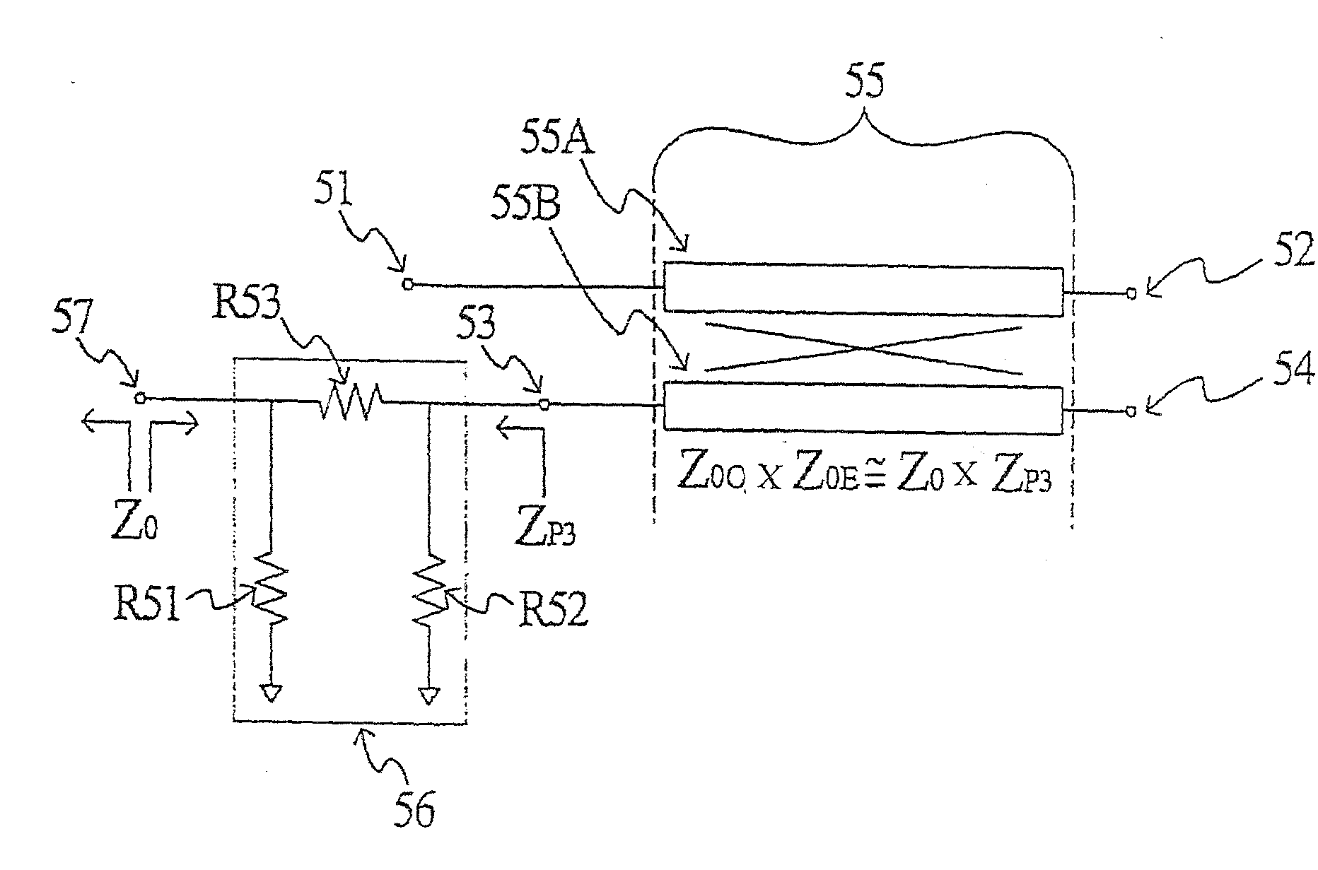
[0044]FIG. 5 shows a circuit diagram of a directional coupler according to the present invention comprising a pair of coupled transmission lines 55, the pair of transmission lines 55 being located in close proximity to each other so that they are electromagnetically coupled to each other. The pair of coupled transmission lines 55 comprises a first transmission line 55A and a second transmission line 55B where the first transmission line 55A comprises a first end, to which a first RF port 51 is connected, and a second end, to which a second RF port 52 is connected, and where the second transmission line 55B comprises a first end, to which a third RF port 53 is connected, and a second end, to which a fourth RF port 54 is connected. An input electrical signal that is fed to first RF port 51 will produce a direct electrical signal at second RF port 52, and a coupled RF signal at third RF port 53. Under ideal operating conditions, the same input signal will produce no signal (or a neglig...

third embodiment

[0066]FIG. 8 shows a circuit diagram of a directional coupler according to the present invention comprising a pair of coupled transmission lines 85, the pair of transmission lines 85 being located in close proximity to each other so that they are electromagnetically coupled to each other. The pair of coupled transmission lines 85 comprises a first transmission line 85A and a second transmission line 85B where first transmission line 85A comprises a first end, to which a first RF port 81 is connected, and a second end, to which a second RF port 82 is connected, and where second transmission line 85B comprises a first end, to which a third RF port 83 is connected, and a second end, to which a fourth RF port 84 is connected. An input electrical signal that is fed to first RF port 81 will produce a direct electrical signal at second RF port 82, and a coupled RF signal at third RF port 83; under ideal operating conditions, the same input signal will produce no signal (or a negligibly sma...


PUM


Abstract

The present invention provides a compact weakly coupled directional coupler combined with an integrated impedance transformation and matching circuit where the impedance transformation and matching circuit facilitates the fabrication of a highly miniaturized directional coupler with optimum electrical performance where the physical dimensions of the coupled transmission lines fall inside the constraints of the fabrication process.

Description

FIELD OF THE INVENTION [0001]The present invention relates to a directional coupler including an impedance matching and impedance transforming attenuator, in particular, a directional coupler for power monitoring, RF circuits or RF front-end circuits.BACKGROUND OF THE INVENTION [0002]In recent times, wireless handsets and terminals have evolved to have a high level of functionality while also becoming extremely compact. Wireless handsets and terminals often include a range of personal media functions, and are capable of operating on multiple systems such as the Global System for Mobile Communications (GSM) and the Universal Mobile Telephone System (UMTS). The components of the various systems in a contemporary wireless handset are required to offer high performance while the physical dimensions are required to become progressively smaller.[0003]In the RF front-end circuit of a wireless handset, a power monitoring circuit is usually employed to control the transmitted power, for exam...

Claims


Application Information

Patent Timeline
Patent Type & Authority Applications(United States)
IPC IPC(8): H01P5/18
CPCH01P5/184
Inventor KEARNS, BRIANCOSTELLO, JOHN
Owner TDK CORPARATION
Why Eureka
Try Eureka