Spread spectrum radar apparatus, method for determining virtual image, and method for suppressing virtual image

a radar apparatus and a technology of spread spectrum, applied in the direction of reradiation, measurement devices, instruments, etc., can solve the problems of false detection of detection, avoid the influence of virtual image signal, so as to reduce the probability of false detection, the effect of avoiding the operation of the radar apparatus

Active Publication Date: 2010-08-05
PANASONIC CORP
View PDF13 Cites 3 Cited by
  • Summary
  • Abstract
  • Description
  • Claims
  • Application Information

AI Technical Summary

Benefits of technology

[0038]The spread spectrum radar apparatus according to the present invention can determine a virtual image signal to be observed, perform a correction calculation on the virtual image signal, reduce or avoid the influence of the virtual image

Problems solved by technology

However, there are cases where a peak may appear which may cause false detection of detecting other than the reflected w

Method used


Image

  • Spread spectrum radar apparatus, method for determining virtual image, and method for suppressing virtual image
  • Spread spectrum radar apparatus, method for determining virtual image, and method for suppressing virtual image
  • Spread spectrum radar apparatus, method for determining virtual image, and method for suppressing virtual image

Examples


embodiment 1

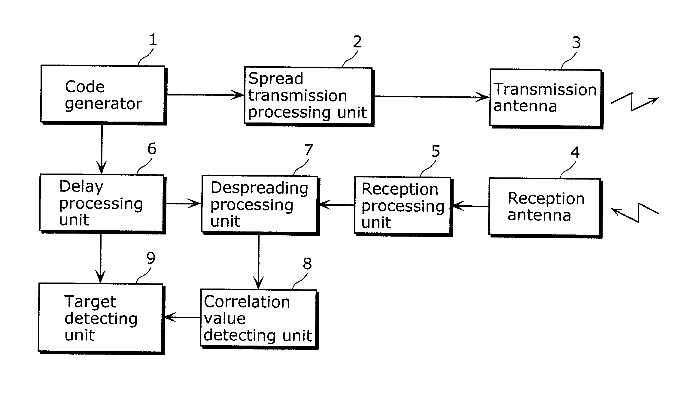
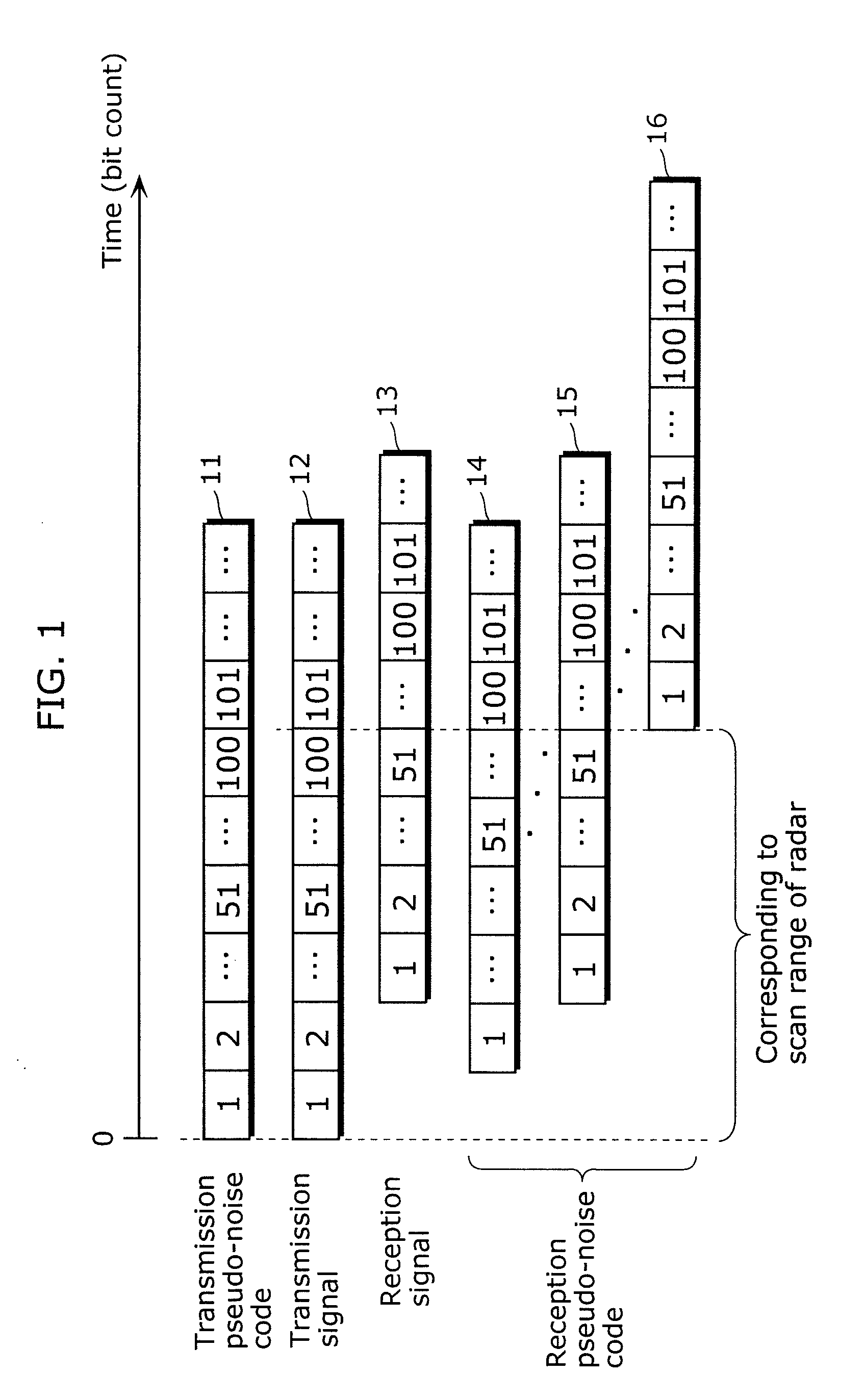
[0075]A spread spectrum radar system (hereinafter referred to as radar system) spread-modulates a narrow band signal generated by a local oscillator to a wide band signal using a transmission pseudo-noise code, and transmits the wide band signal as radar waves. Then, the radar system receives, as a reception signal, the wide band signal obtained by reflecting the transmitted reflected waves from an object, and spread-demodulates the reception signal to the narrow band signal, using a reception pseudo-noise code obtained by delaying the transmission pseudo-noise code. The radar system generates a radar signal by frequency conversion by mixing a correlation signal that is a result of the demodulation and the narrow band signal generated by the local oscillator. Based on the radar signal, the radar system can determine the presence or absence of an object, a distance to the object, a relative velocity of the object, and others.

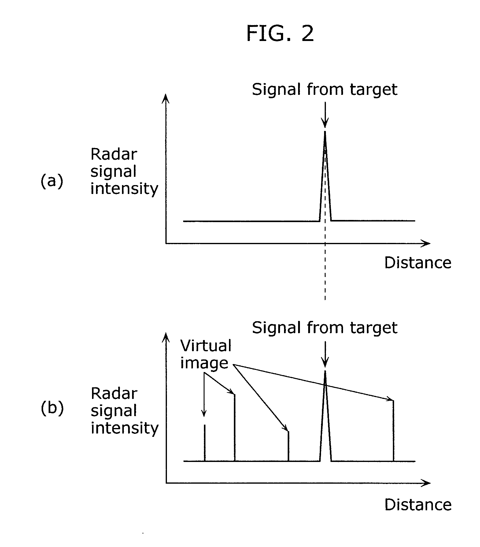
[0076]However, in a conventional spread spectrum radar syst...

embodiment 2

[0118]A spread spectrum radar apparatus according to Embodiment 2 in the present invention will be described hereinafter with reference to drawings.

[0119]FIG. 12 illustrates a functional block diagram of a radar system 800 according to Embodiment 2. The spread spectrum radar apparatus according to Embodiment 2 is characterized in that a virtual image is determined before transmitting radar waves using a switching controller.

[0120]As illustrated in FIG. 12, the virtual image determining unit 130 in the radar system 800 according to Embodiment 2 includes a signal attenuator 140 that attenuates a signal, a transmission switch 151 that switches a connection between the signal attenuator 140 and the transmission antenna 113, a reception switch 152 that switches a connection between the signal attenuator 140 and the reception antenna 120, a switching controller 133 that determines each connection destination of the transmission switch 151 and the reception switch 152, and the virtual-imag...


PUM


Abstract

The spread spectrum radar apparatus in the present invention (i) includes: a transmission code generator (110); a reception code generator (121) generating a reception code obtained by delaying a transmission code; a spread modulator (112) spread-modulating a signal generated by a local oscillator (111) using the transmission code; a transmission antenna (113) transmitting the spread-modulated signal; a reception antenna (120) receiving a signal; a spread demodulator (122) demodulating the signal using the reception code to provide a correlation signal; a mixer (123) mixing the correlation signal and the signal generated by the local oscillator (111) to generate a radar signal; a virtual image determining unit (130) determining a virtual image; and a radar signal calculation device (160) calculating the radar signal using a virtual image determination signal, and (ii) adds a calculation and an offset signal for suppressing a peak intensity of the virtual image when the virtual image occurs.

Description

TECHNICAL FIELD[0001]The present invention relates to a spread spectrum radar apparatus using a spread spectrum method, and particularly to a spread spectrum radar apparatus which suppresses at least one alias signal that may cause false detection of the presence of an object and that is different from a reception signal.BACKGROUND ART[0002]In recent years, various techniques of spread spectrum radar apparatuses using spread spectrum methods have been suggested (for example, see Patent Reference 1).[0003]The spread spectrum radar apparatuses spread-modulate narrow band signals to wide band signals using transmission pseudo-noise codes. The spread spectrum radar apparatuses transmit the spread-modulated wide band signals as radar waves. Then, the spread spectrum radar apparatuses receive, as reception signals, reflected waves obtained by reflecting the transmitted radar waves from objects. Then, the spread spectrum radar apparatuses spread demodulate the reception signals to correlat...

Claims


Application Information

Patent Timeline
IPC IPC(8): G01S13/00
CPCG01S13/325G01S2013/9378G01S2013/9375G01S13/931G01S2013/93271G01S2013/93272
Inventor NEGORO, NOBORUFUKUDA, TAKESHISAKAI, HIROYUKI
Owner PANASONIC CORP
Why Eureka
Try Eureka