Method and system for encoding a 3D video signal, enclosed 3D video signal, method and system for decoder for a 3D video signal

a technology of video signal and encoder, applied in the field of video encoding and decoding, to achieve the effect of improving 3d image quality, reducing the amount of data to be transmitted, and improving depth maps

Active Publication Date: 2010-08-05
KONINKLIJKE PHILIPS ELECTRONICS NV
View PDF11 Cites 240 Cited by
  • Summary
  • Abstract
  • Description
  • Claims
  • Application Information

AI Technical Summary

Benefits of technology

[0022]In practice this means that in the occlusion data frame there are areas for which no relevant occlusion (i.e. non functional) data are generated. The method encompasses a “switching function” wherein the switch has at least two settings, one setting in which the data is recognized as being non-functional, i.e. independent of the actual video content and / or irrelevant, and one setting in which functional data, i.e. data dependent on the video content and relevant. Being able to distinguish the non-functional data from functional data allows increasing the coding efficiency of the following encoding and / or decrease the numbers of bits transmitted.
[0043]It is observed for preferred embodiments that the coding efficiency of the occlusion data frame improved significantly when for the occlusion data frames reference frames(s) were used from the centre view. Initially this might sound rather surprising since the occlusion data comprise those data that are not visible in the centre view and thus are not available in the centre view frame. However, the correlation of the occlusion data with the centre view data close to the foreground object in the centre view may be high due to motion of the foreground object. Usage of reference frame(s) from the centre view for encoding the occlusion data frame has been found to improve the coding efficiency of the occlusion data significantly.

Problems solved by technology

However, a reverse process will be used at the decoder side and at the decoder side the “original” is no longer available, only an encoded version.
Using the original at the encoder side, instead of an encoded / decoded leads to an uncertainty since the process at the decoder side would not be exactly the same.

Method used


Image

  • Method and system for encoding a 3D video signal, enclosed 3D video signal, method and system for decoder for a 3D video signal
  • Method and system for encoding a 3D video signal, enclosed 3D video signal, method and system for decoder for a 3D video signal
  • Method and system for encoding a 3D video signal, enclosed 3D video signal, method and system for decoder for a 3D video signal

Examples


Embodiment Construction

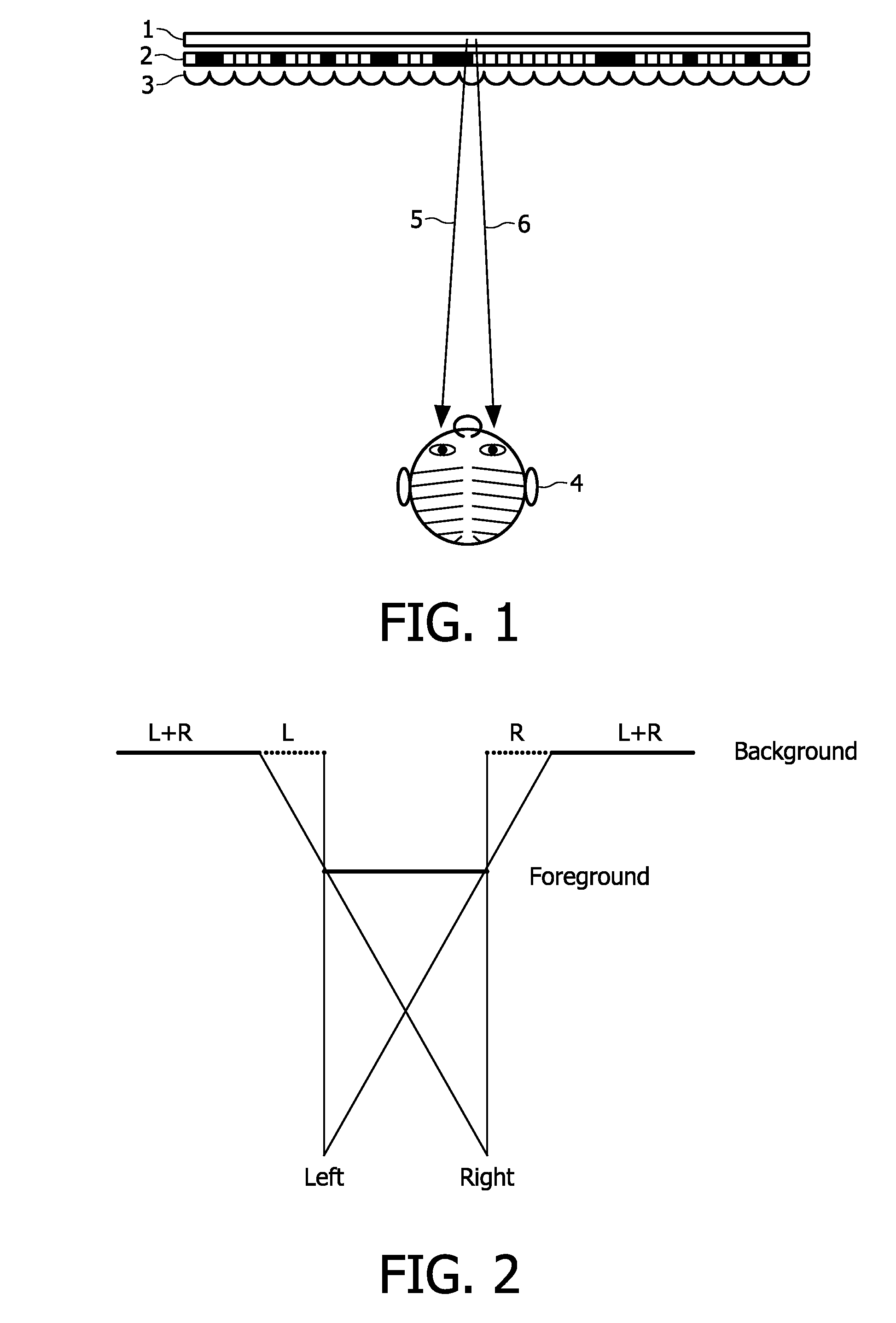
[0068]FIG. 1 illustrates the basic principle of a type of auto-stereoscopic display device. The display device comprises a lenticular screen splitting 3 for forming two stereo images 5 and 6. The vertical lines of two stereo images are (spatially) alternatingly displayed on, e.g., a spatial light modulator 2 (e.g. a LCD) with a backlight 1. Together the back light and the spatial light modulator form a pixel array. The lens structure of the lenticular screen 3 directs the stereo image to the appropriate eye of the viewer.

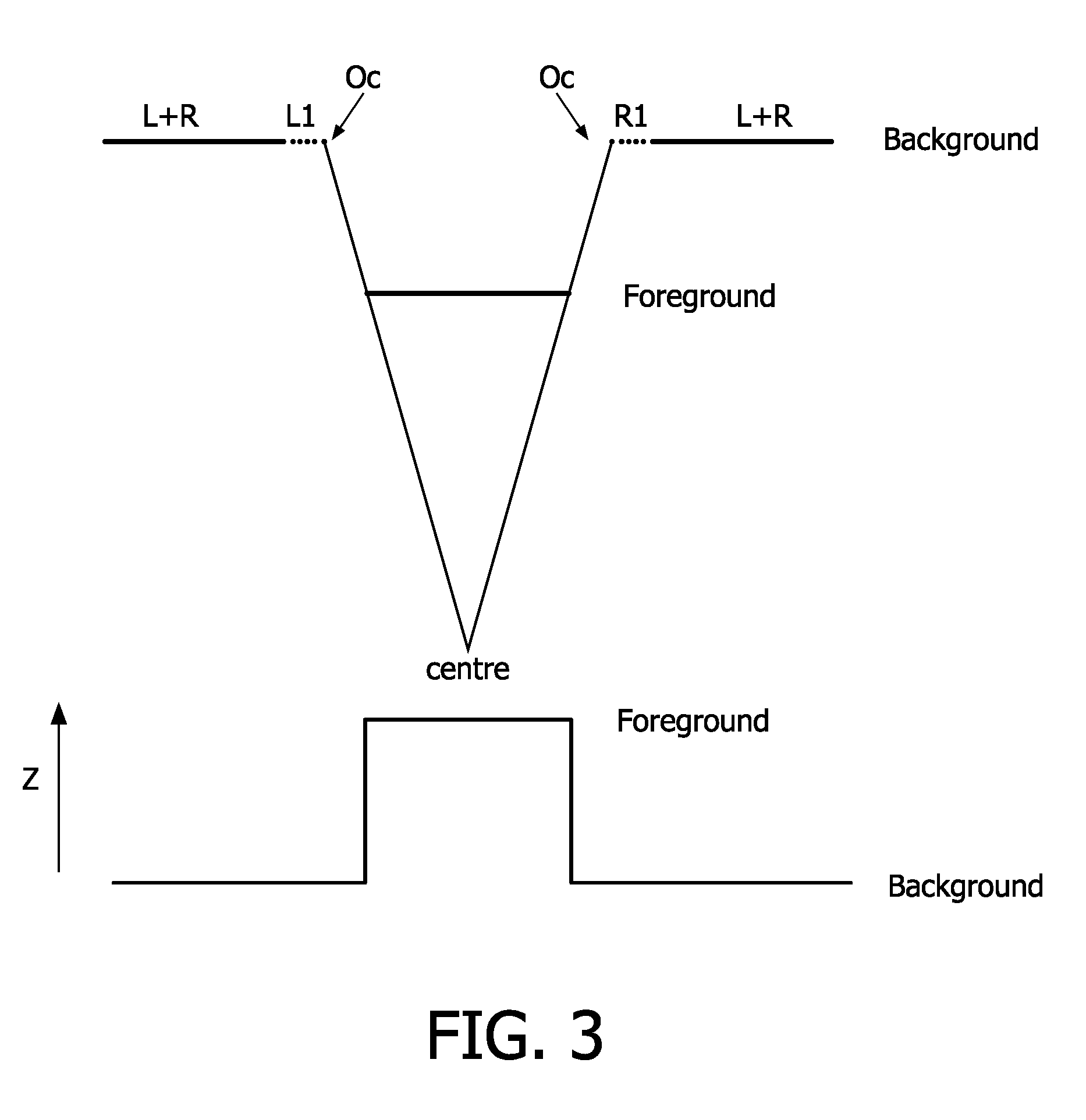
[0069]In FIGS. 2 and 3 the occlusion problem is illustrated. The line indicated with Background in this figure is the background and the line indicated with Foreground represents an object that is located in front of the background. Left and Right represent two views of this scene. These two views can be, for example, the left and the right view for a stereo set-up, or the two most outer views for the case of usage of an n-view display. The remaining n−2 views, requ...


PUM


Abstract

In a method for encoding and an encoder for a 3D video signal, centre view frames, a depth map for centre view frames and an occlusion data frame are encoded. On the basis of the depth map for the centre view frame a distinction is made between functional and non-functional data in an occlusion data frame. This allows a strong reduction in bits needed for the encoded occlusion data frame. In the decoder a combined data stream is made of functional data in the encoded occlusion data frames and the centre view frames. Preferably the centre view frames are used as reference frames in encoding the occlusion data frames.

Description

FIELD OF THE INVENTION[0001]The invention relates to the field of video encoding and decoding. It presents a method and system for encoding a 3D video signal. The invention also relates to a method and system for decoding a 3D video signal. The invention also relates to an encoded 3D video signal.BACKGROUND OF THE INVENTION[0002]Recently there has been much interest in providing 3-D images on 3-D image displays. It is believed that 3-D imaging will be, after color imaging, the next great innovation in imaging. We are now at the advent of introduction of auto-stereoscopic displays for the consumer market.[0003]A 3-D display device usually has a display screen on which the images are displayed.[0004]Basically, a three dimensional impression can be created by using stereo pairs, i.e. two slightly different images directed at the two eyes of the viewer.[0005]There are several ways to produce stereo images. The images may be time multiplexed on a 2D display, but this requires that the vi...

Claims


Application Information

Patent Timeline
Patent Type & Authority Applications(United States)
IPC IPC(8): H04N7/26
CPCH04N19/597H04N19/20H04N13/10
Inventor KLEIN GUNNEWIEK, REINIER BERNARDUS MARIAVAREKAMP, CHRISTIAANBRULS, WILHELMUS HENDRIKUS ALFONSUS
Owner KONINKLIJKE PHILIPS ELECTRONICS NV
Why Eureka
Try Eureka