Magnetic resonance imaging apparatus and magnetic resonance imaging method
a magnetic resonance imaging and magnetic resonance imaging technology, applied in the field of magnetic resonance imaging apparatus and magnetic resonance imaging method, can solve the problems of long imaging time, long binding hour, and long imaging tim
- Summary
- Abstract
- Description
- Claims
- Application Information
AI Technical Summary
Benefits of technology
Problems solved by technology
Method used
Image
Examples
first embodiment
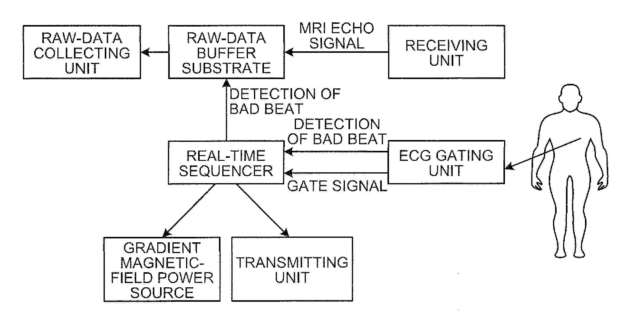
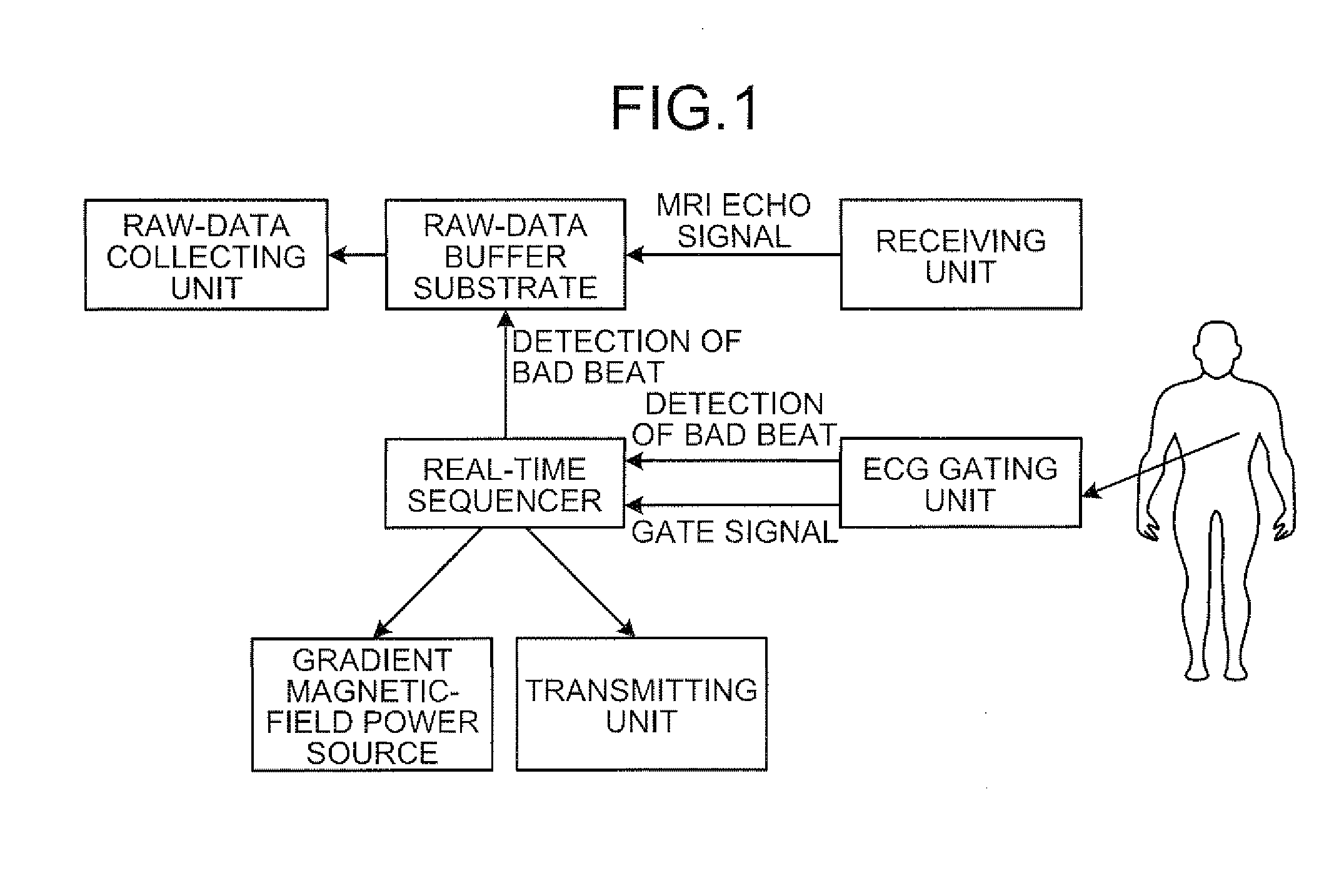
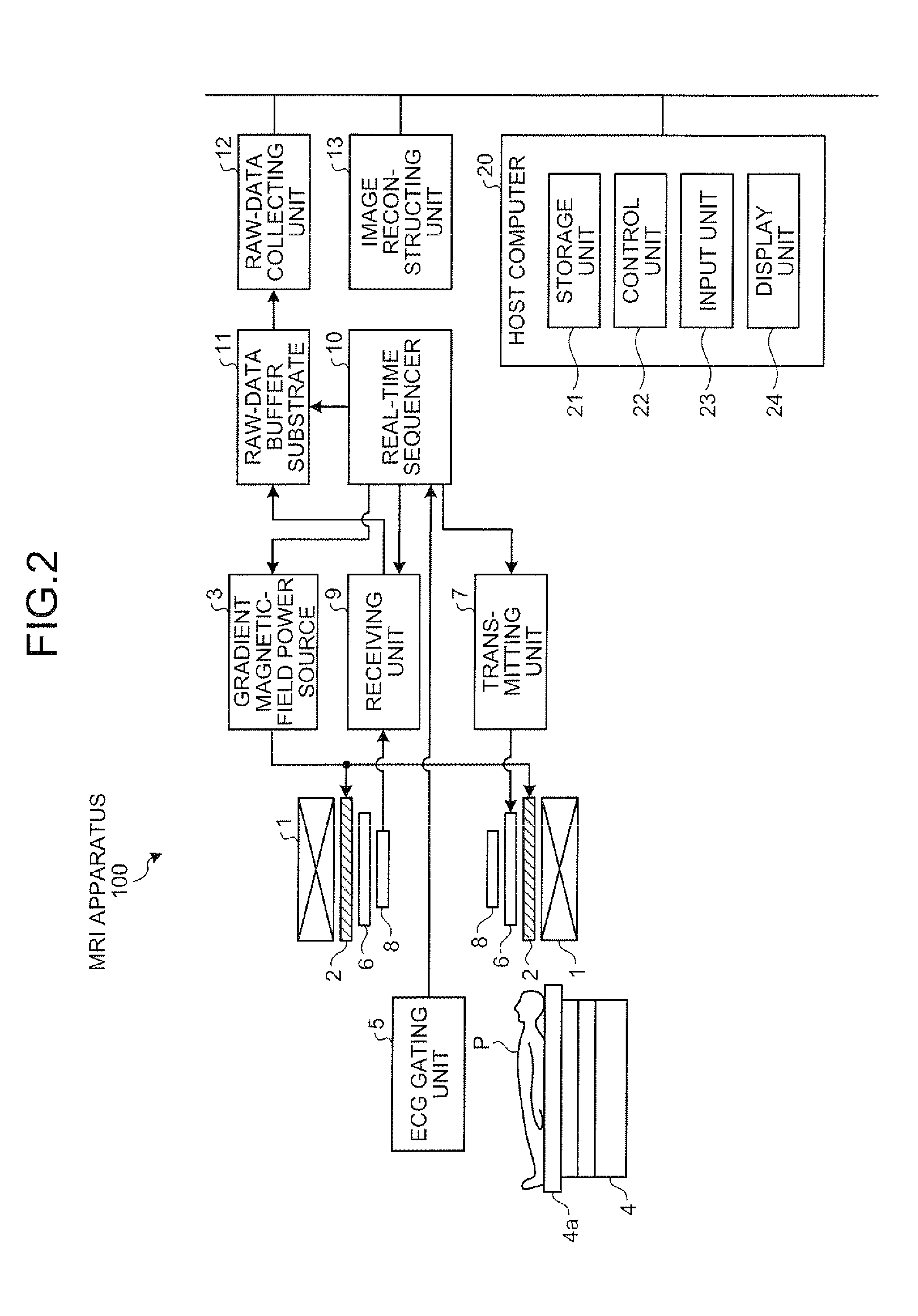
[0027]As shown in FIG. 1, in the MRI apparatus an Electrocardiogram (FOG) gating unit creates a gate signal synchronized with an electrocardiographic signal of a subject, and transmits the created gate signal to a real-time sequencer. The real-time sequencer then transmits sequence information (information for specifying strength, timing, and the like) to a gradient magnetic-field power source, a transmitting unit for a Radio Frequency wave (RF) pulse, and the like, so as to be synchronized with the received gate signal. The gradient magnetic-field power source, the transmitting unit, and the like execute a sequence in accordance with the received sequence information, so that the subject is imaged.
[0028]In the MRI apparatus according to the first embodiment, a raw-data buffer substrate intermediates between a receiving unit that acquires a magnetic resonance signal (hereinafter, “MRI echo signal”) and a raw-data collecting unit that collects raw data, buffers raw data acquired by ...
second embodiment
[0092]In the present invention, explained below is a method that the raw-data buffer substrate 11 includes regions configured to buffer therein raw data of a plurality of heart-beat equivalent more than at least two heart beats (for example, five heart-beat equivalent), and provides control not to transfer raw data of a preset number of heart-beat equivalent when a BAD beat is detected. In other words, it is a method of reacquiring raw data by turning back by a certain number of heart-beat equivalent.
[0093]A process procedure performed by the MRI apparatus according to the second embodiment is explained below with reference to FIGS. 10 and 11. FIG. 10 is a schematic diagram for explaining transfer control on transferring raw data.
[0094]Explaining the transfer control by focusing on difference from the MRI apparatus 100 according to the first embodiment shown in FIG. 7, in the MRI apparatus 100 according to the second embodiment, the raw-data buffer substrate 11 includes regions conf...
third embodiment
[0104]For example, according to an imaging method of acquiring three MRI echo signals with respect to one heart beat, each three MRI echo signals per heart beat are arranged, for example, from the first MRI echo signal (echo 1) to the third MRI echo signal (echo 3), from the fourth MRI echo signal (echo 4) to the sixth MRI echo signal (echo 6), and from the seventh MRI echo signal (echo 7) to the ninth MRI echo signal (echo 9). An example where the present invention is applied to the imaging method of acquiring three MRI echo signals with respect to one heart beat is explained below as the present invention.
[0105]A timing chart of ECG gating according to the third embodiment is explained below with reference to FIGS. 12 and 13. FIG. 12 is an ECG-gating timing chart. To begin with, similarly to the first and second embodiments, the ECG gating unit 5 detects an FOG signal as an electric signal, performs A / D conversion processing on the detected ECG signal, creates a QRS synchronized s...
PUM
 Abstract
Description
Claims
Application Information
 - R&D
- Intellectual Property
- Life Sciences
- Materials
- Tech Scout
- Unparalleled Data Quality
- Higher Quality Content
- 60% Fewer Hallucinations
Browse by: Latest US Patents, China's latest patents, Technical Efficacy Thesaurus, Application Domain, Technology Topic, Popular Technical Reports.
© 2025 PatSnap. All rights reserved.Legal|Privacy policy|Modern Slavery Act Transparency Statement|Sitemap|About US| Contact US: help@patsnap.com


