Eureka AIR delivers breakthrough ideas for toughest innovation challenges, trusted by R&D personnel around the world.

Crimp-through crimp connector for connecting a conductor cable and an electrode of an implantable cardiac electrotherapy lead

Active Publication Date: 2010-08-05
PACESETTER INC
View PDF9 Cites 7 Cited by
  • Summary
  • Abstract
  • Description
  • Claims
  • Application Information

AI Technical Summary

Benefits of technology

[0007]In another embodiment, an implantable cardiac electrotherapy lead includes a tubular body, an electrode on the tubular body with a termination ring, the termination ring having an arcuate inner surface and a proximal edge, a cable conductor including an end, the cable conductor having a conductive core and an insulation jacket, and a crimp connector with an inner surface defining a cavity and an arcuate outer surface, the crimp connector coupling the cable conductor to the termination ring. The arcuate outer surface of the crimp connector nests substantially continuously against the arcuate inner surface of the termination ring. The crimp connector may include a segment of pre-drawn tubing. In another embodiment, the crimp connector further includes at least one splice opening oriented substantially transverse to a longitudinal axis of the crimp connector. In another embodiment, the at least one splice opening is at least one laser cut splice opening having a sharp edge at its intersection with the inner surface of the crimp connector. In still another embodiment, in a post-crimped position, the sharp edge penetrates the insulation jacket on the

Problems solved by technology

Such transitions are excessively expensive to create for a number of reasons.
First, each transition employs a relatively expensive crimp connector individually cut using a wire electrical discharge machining process.
Second, the process for creating the transition is labor intensive.
Third, difficulty associated with the process of creating the transition results in substantial scrap.
Crimp connectors may be unidirectional and are often reversed when crimped onto the cable conductor, resulting in the scrapping of the crimp connector and the cable conductor.
Failure to satisfy the tight tolerances can result in a weak weld between the crimp connector and the shock coil, or welding can burn a hole through the connector again requiring the lead to be scrapped.

Method used


Image

  • Crimp-through crimp connector for connecting a conductor cable and an electrode of an implantable cardiac electrotherapy lead
  • Crimp-through crimp connector for connecting a conductor cable and an electrode of an implantable cardiac electrotherapy lead
  • Crimp-through crimp connector for connecting a conductor cable and an electrode of an implantable cardiac electrotherapy lead

Examples


Embodiment Construction

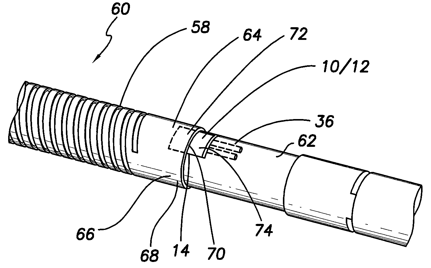
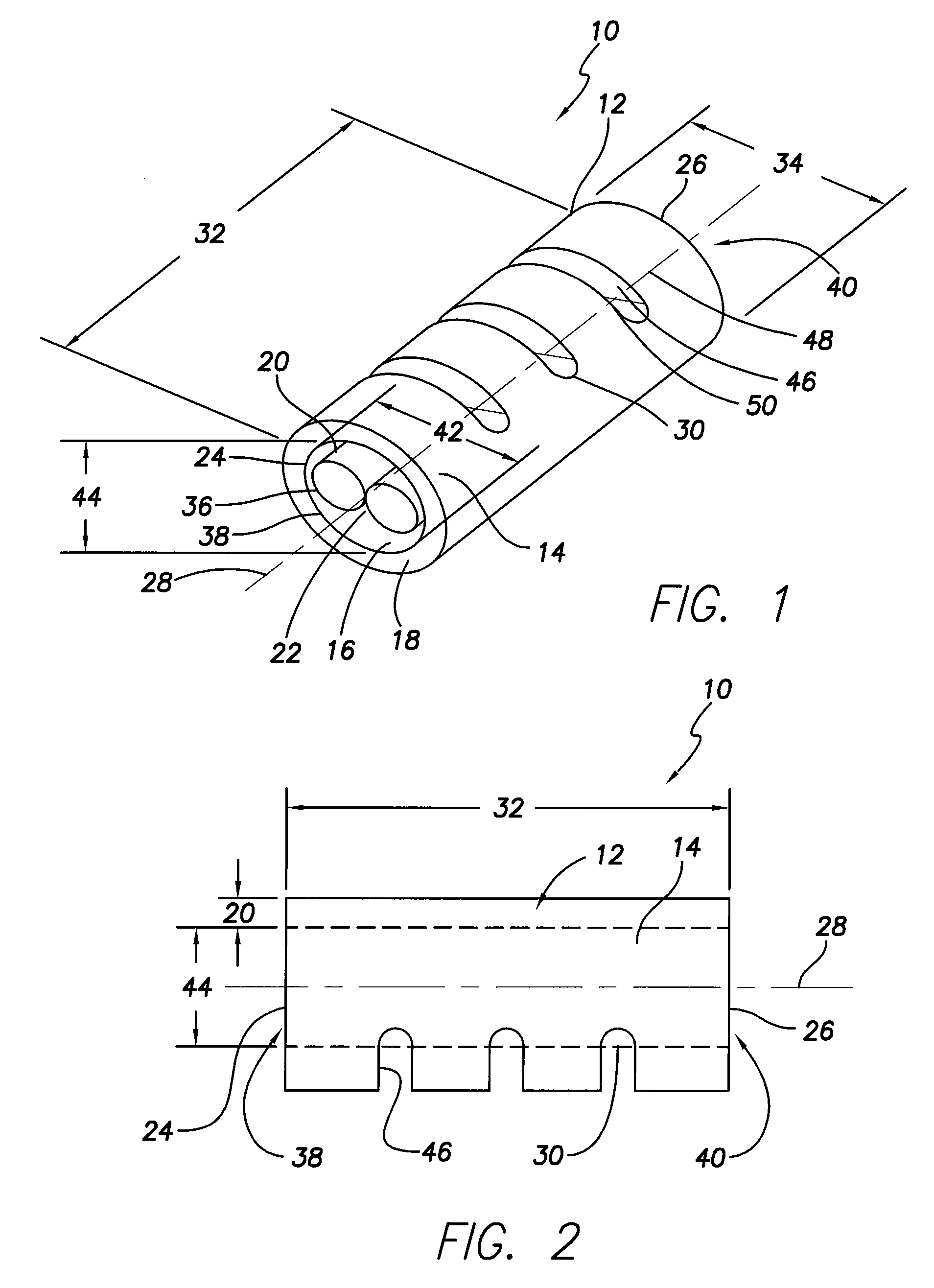
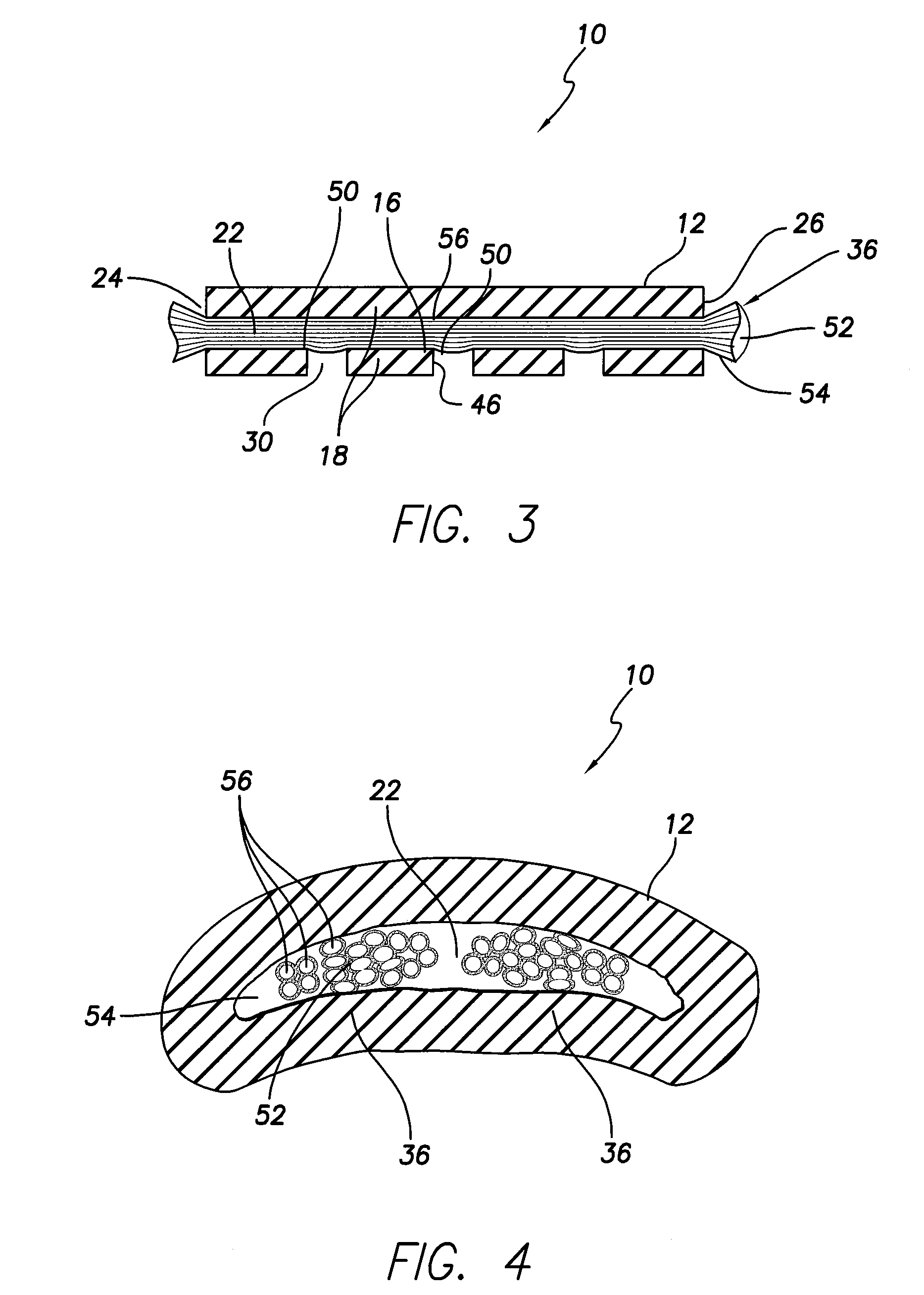
[0017]The following detailed description relates to the connection between cable conductors and an electrode on a medical lead. A medical lead may be used to monitor heart function and stimulate heart function. As such, a distal end of a lead may be placed within the heart and a proximal end may be connected to a controller such as a pacemaker, ICD or other type pulse generator via a lead connector end on the proximal lead end. The distal end of the lead may have a series of electrodes including a pacing electrode, a sensing electrode, and a shocking electrode or coil. Each of the electrodes may be connected via a cable / electrode connector to a respective cable conductor or respective series of cable conductors extending the length of the lead to the lead proximal end's lead connector end mechanically and electrically coupling the lead proximal end to the controller. The cable conductors may include a conductive core covered by an insulation layer or layers. As such, the connection ...


PUM

PropertyMeasurementUnit
Electrical conductoraaaaaaaaaa

Abstract

An implantable cardiac electrotherapy lead is disclosed herein. The lead may include an electrode on a distal portion of the lead, a conductor extending proximally through the lead from the electrode, and a crimp connector coupling a distal end of the conductor to the electrode. The connector may include a body with an outer surface, an inner surface, proximal and distal ends, a cavity, and at least one splice opening. The inner surface defines the cavity, the proximal and distal ends respectively define proximal and distal openings leading to the cavity, and the at least one splice opening extends from the outer surface to the inner surface and is oriented generally transverse to an axis extending between the proximal and distal openings.

Description

FIELD OF THE INVENTION[0001]The present invention relates to medical apparatus and methods of manufacturing such apparatus. More specifically, the present invention relates to implantable cardiac electrotherapy leads and methods of manufacturing such leads.BACKGROUND OF THE INVENTION[0002]Current implantable cardiac electrotherapy leads (e.g., cardiac resynchronization therapy (“CRT”) leads, bradycardia leads, tachycardia leads) utilize crimp connectors to transition from conductor cables to welded joints at the electrodes or shock coils. Such transitions are excessively expensive to create for a number of reasons. First, each transition employs a relatively expensive crimp connector individually cut using a wire electrical discharge machining process.[0003]Second, the process for creating the transition is labor intensive. To achieve adequate electrical contact between a crimp connector and the conductive core of a cable conductor, insulation must be removed from the cable conducto...

Claims


Application Information

Patent Timeline
IPC IPC(8): A61N1/362B23K31/02
CPCA61N1/056H01R4/20Y10T29/49179H01R43/01H01R2201/12
Inventor LI, YONG
Owner PACESETTER INC
Why Eureka
Eureka Blog
Learn More