Wireless communication device and circular buffer control method
a communication device and control method technology, applied in the direction of instruments, coding, code conversion, etc., can solve the problems of rare matching between the transmission bit sequence and the divided buffer size, and achieve the effect of improving decoding performan
- Summary
- Abstract
- Description
- Claims
- Application Information
AI Technical Summary
Benefits of technology
Problems solved by technology
Method used
Image
Examples
embodiment 1
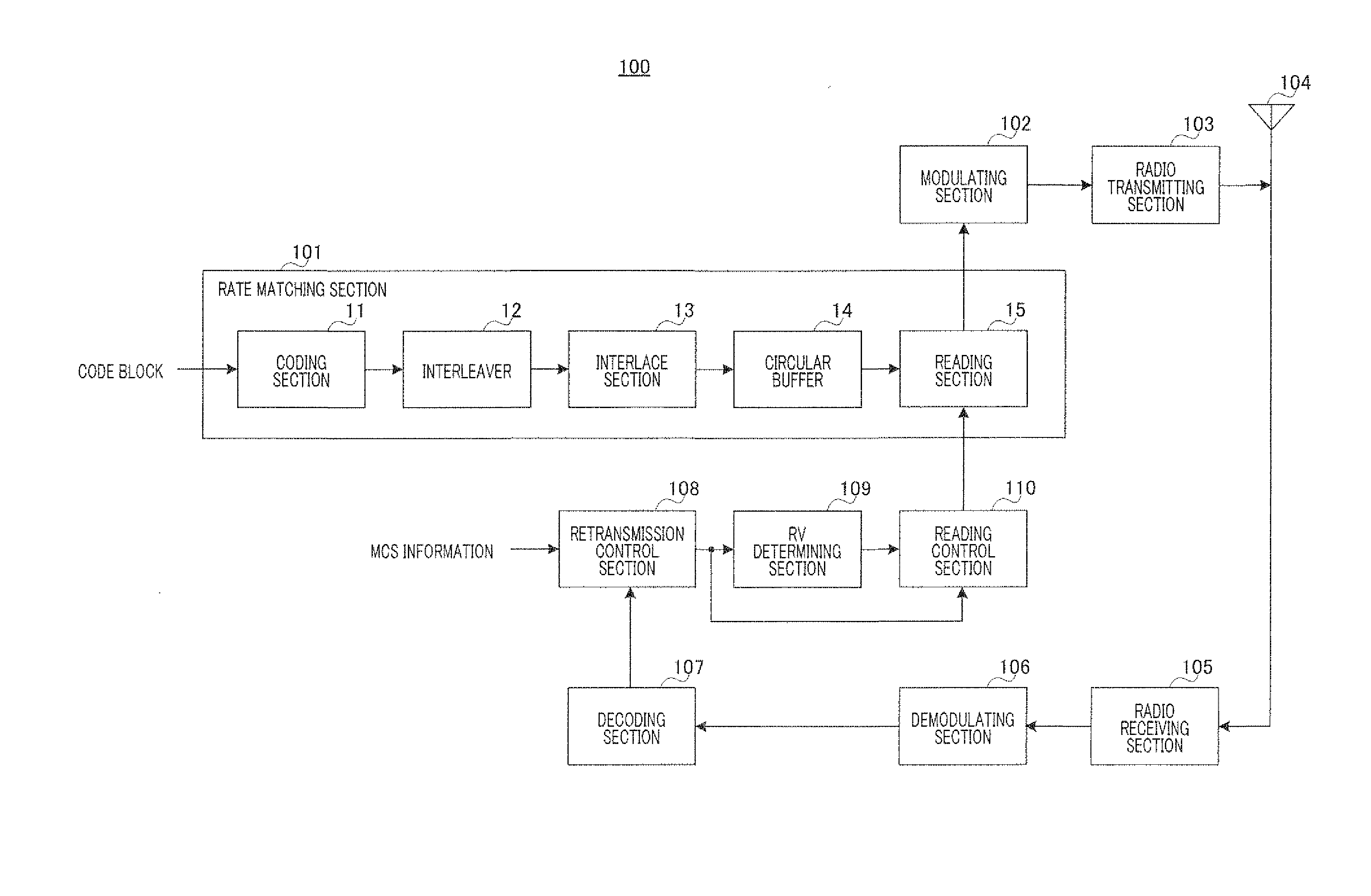
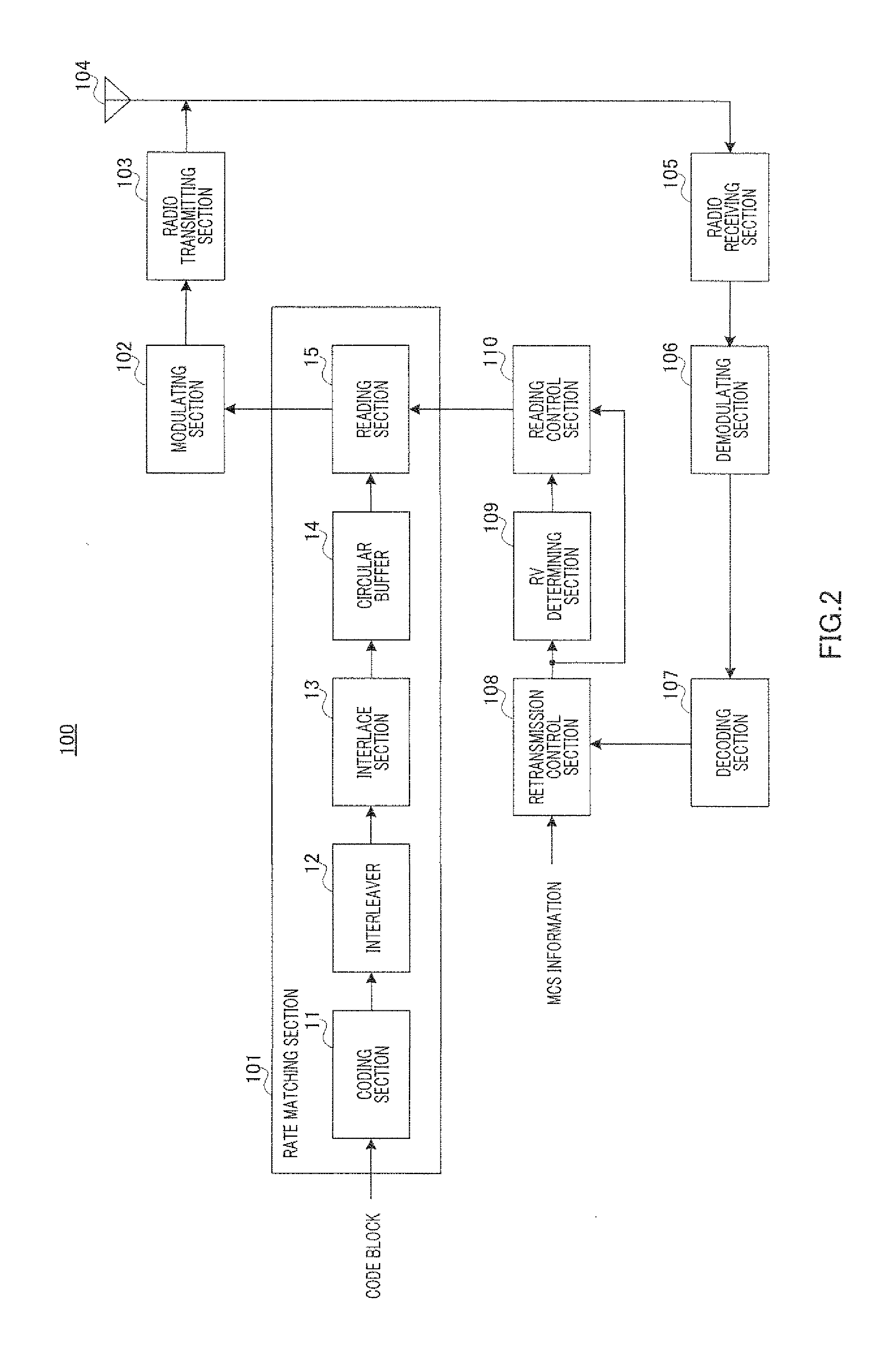
[0026]FIG. 2 shows the configuration of radio communication apparatus 100 according to the present embodiment.
[0027]In radio communication apparatus 100 shown in FIG. 2, rate matching section 101 is configured with coding section 11, interleaver 12, interlace section 13, circular buffer 14 and reading section 15.
[0028]Coding section 11 receives as input in order a plurality of code blocks generated by dividing a transport block.
[0029]Coding section 11 performs error correction coding on a information bit sequence in a code block using turbo coding, and outputs an encoded bit sequence composed of systematic bits and parity bits, to interleaver 12. Here, the coding rate (mother rate) of coding section 11 is ⅓. Therefore, one information bit is encoded to one systematic bit (S bit) and two parity bits (P1 bit and P2 bit).
[0030]Interleaver 12 interleaves the encoded bit sequence per S bit sequence, P1 bit sequence and P2 bit sequence, and outputs the interleaved S bit sequence, P1 bit s...
example 1-1
FIGS. 4 to 7
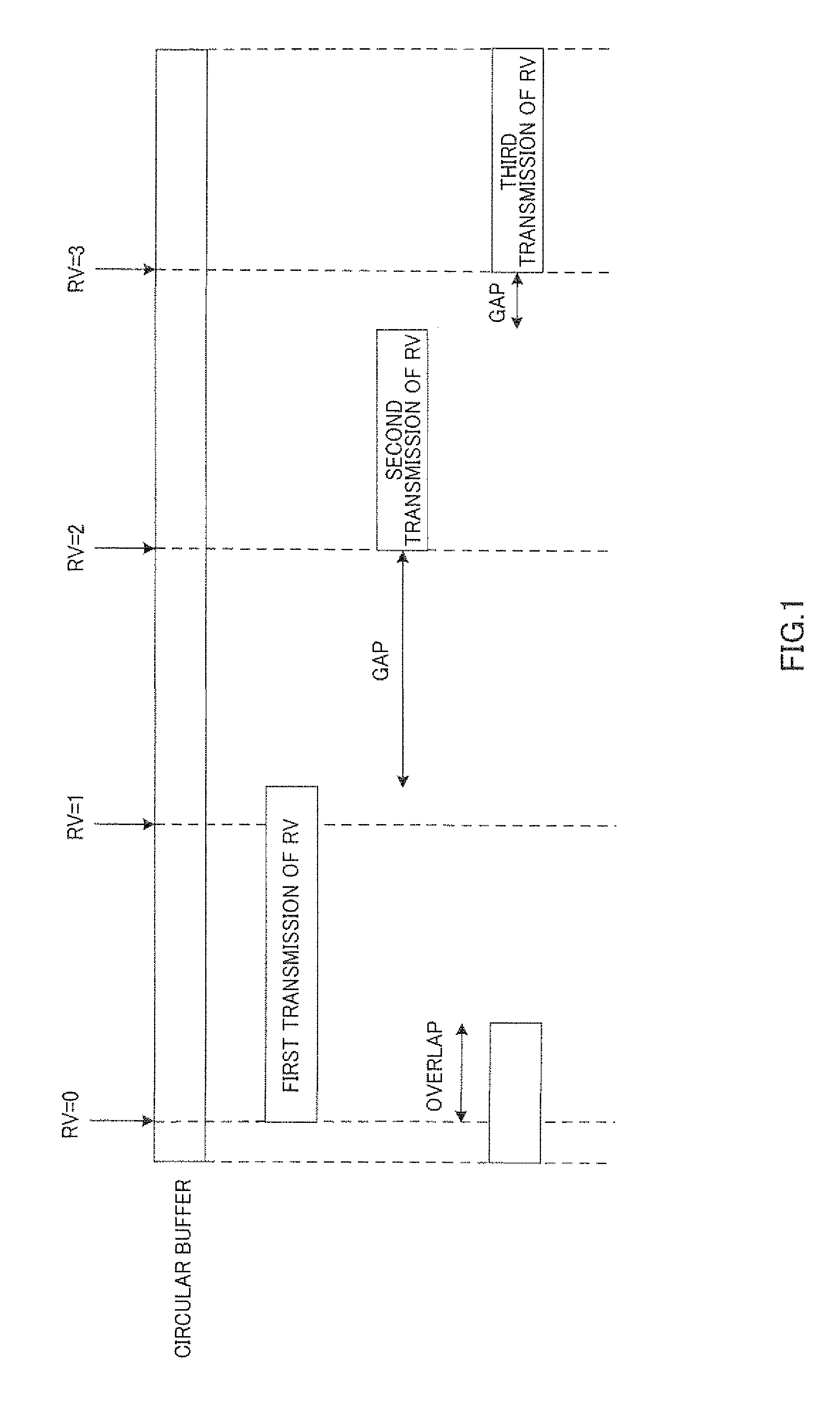
[0043]With the present embodiment, a retransmission RV is configured using the read start address and the read direction where the smallest number of gap bits or the smallest number of overlapping bits with a transmitted bit sequence is a minimum among a plurality of RV selection candidates.
[0044]There are two read directions, the forward direction and the backward direction, and therefore, assuming that the number of read start addresses (i.e. the number of RVs) is Np, the number of RV selection candidates is 2Np. Accordingly, upon each transmission, one retransmission RV is selected among 2Np RV selection candidates.
[0045]Then, first, the smallest number of gap bits or the smallest number of overlapping bits are found on a per RV selection candidate basis. As for each RV selection candidate, a smaller gap or a smaller overlap among gaps or overlaps placed before and after an RV selection candidate is made the smallest gap or the smallest overlap.
[0046]For example, as s...
example 1-2
FIG. 8
[0052]With the present example, in the above example 1-1, the read start address of the retransmission RV is limited to a read start address of a transmitted bit sequence and a read start address neighboring the read start address.
[0053]The read start address upon the first transmission and the read start address upon a second transmission are both RV=0 in the above FIG. 7, and therefore, among four, RV=0, 1, 2 and 3, the read start address upon a third transmission is limited to three, RV=0 and, RV=1 and RV=3 that neighbor RV=0. Accordingly, the eight RV selection candidates 1 to 8 shown in the above FIG. 6 are limited to the six RV selection candidates 1 to 6 shown in FIG. 8.
[0054]Then, similar to the above example 1-1, upon comparing the smallest numbers of gap bits and the smallest numbers of overlapping bits among the six RV selection candidates 1 to 6 shown in FIG. 8, the smallest value in those candidates is 3 bits. Consequently, in a concrete example shown in FIG. 8, t...
PUM
 Abstract
Description
Claims
Application Information
 - R&D
- Intellectual Property
- Life Sciences
- Materials
- Tech Scout
- Unparalleled Data Quality
- Higher Quality Content
- 60% Fewer Hallucinations
Browse by: Latest US Patents, China's latest patents, Technical Efficacy Thesaurus, Application Domain, Technology Topic, Popular Technical Reports.
© 2025 PatSnap. All rights reserved.Legal|Privacy policy|Modern Slavery Act Transparency Statement|Sitemap|About US| Contact US: help@patsnap.com


