
Support system for mounting building facade elements to a framework

a technology for supporting systems and building facades, applied in the direction of screws, threaded fasteners, mechanical equipment, etc., can solve the problems of large and disproportionate heat loss, labour-intensive systems, and adverse thermal performance effects

Inactive Publication Date: 2010-08-12
KINGSPAN HLDG (IRL) LTD
View PDF10 Cites 19 Cited by
  • Summary
  • Abstract
  • Description
  • Claims
  • Application Information

AI Technical Summary

Benefits of technology

[0008]Cylindrical elements are intrinsically simpler to seal then plate / fin elements, and can easily incorporate a sealing washer into their design.
[0009]This invention is directed towards providing a bracket with the capacity to carry relatively high vertical loads associated with the weight of facade cladding materials and horizontal wind loads, whilst minimising the thermal losses though the system when connected to a thermally conductive substrate or frame. This is combined with features to provide good leakage resistance performance to air, water and vapour, on a repeatable and easily attainable basis. The bracket provides versatility in its provision for mounting alternative materials and a variety of cavity sizes.STATEMENTS OF INVENTION

Problems solved by technology

There are a number of problems with conventional systems.
The brackets provide a heat conductor which may adversely affect the thermal performance.
The systems are also labour intensive and require an installer to carry out a number of steps for correct fitting and finishing.
Thermal performance is generally adequate when angle brackets are fastened to low conductivity substrates such as concrete and timber, but major and disproportionate heat losses can result when angle brackets are fixed to conductive materials such as steel.
The fin projection of angle brackets is difficult to seal to membrane type barriers, and also to rigid faces that have been cut and made good.
Seals applied tend to be mastic and wet applied polymer types, these have a limited life expectancy and are difficult to replace when the facade is in place.
Some fasteners rely on their bearing onto rigid insulation materials, this substantially limits their load carrying capacity and possibly their long term durability and function.
Thermally, the threaded rod element has a relatively large cross section for structural purposes where it acts as a cantilever: this is relatively unimportant where low conductivity substrates are concerned.

Method used


Image

  • Support system for mounting building facade elements to a framework
  • Support system for mounting building facade elements to a framework
  • Support system for mounting building facade elements to a framework

Examples


Embodiment Construction

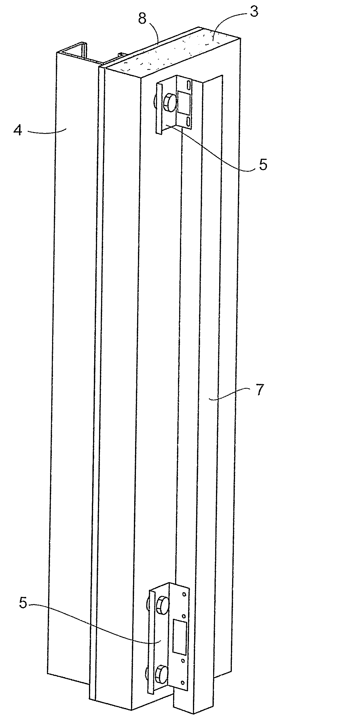
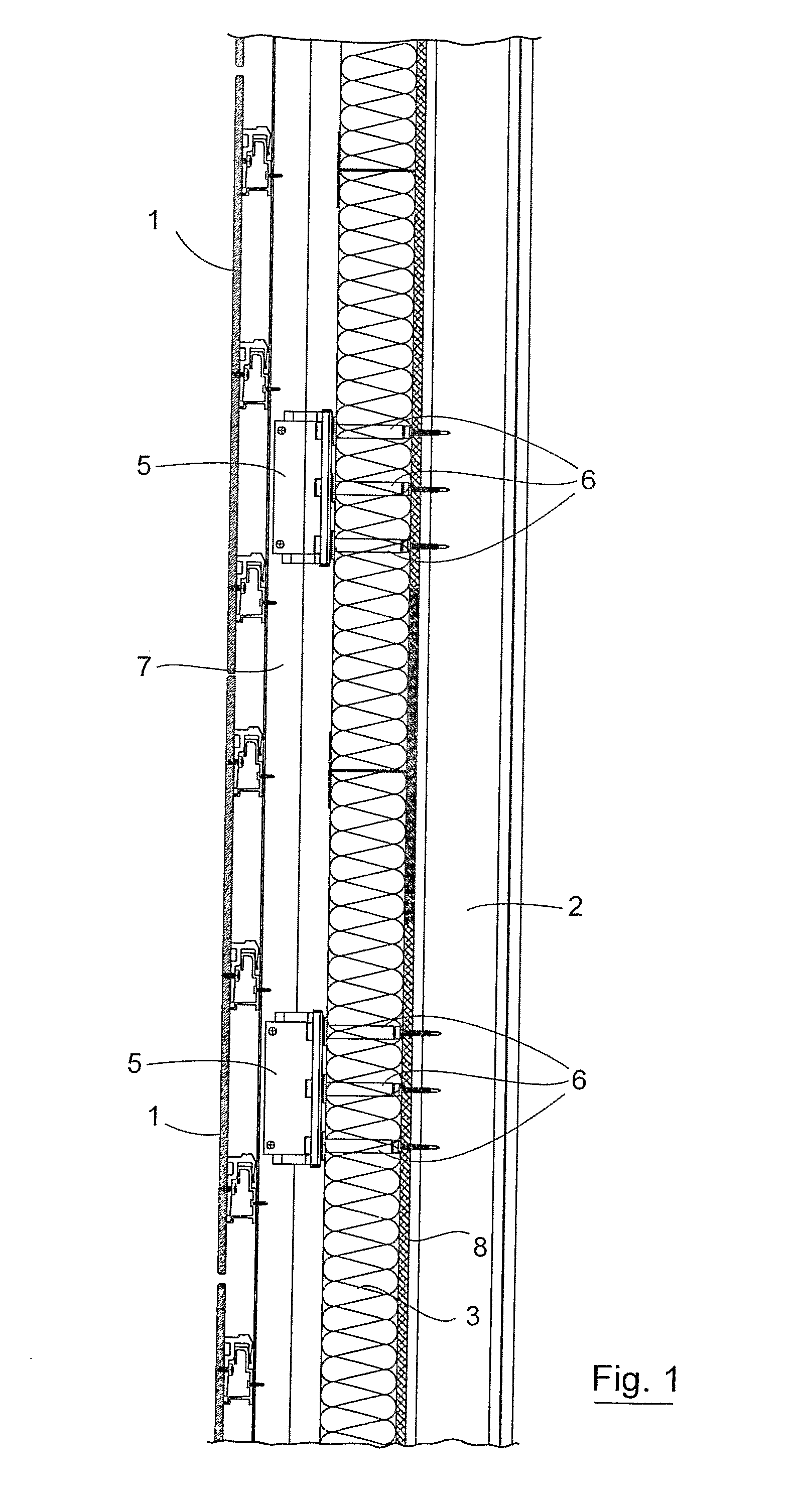
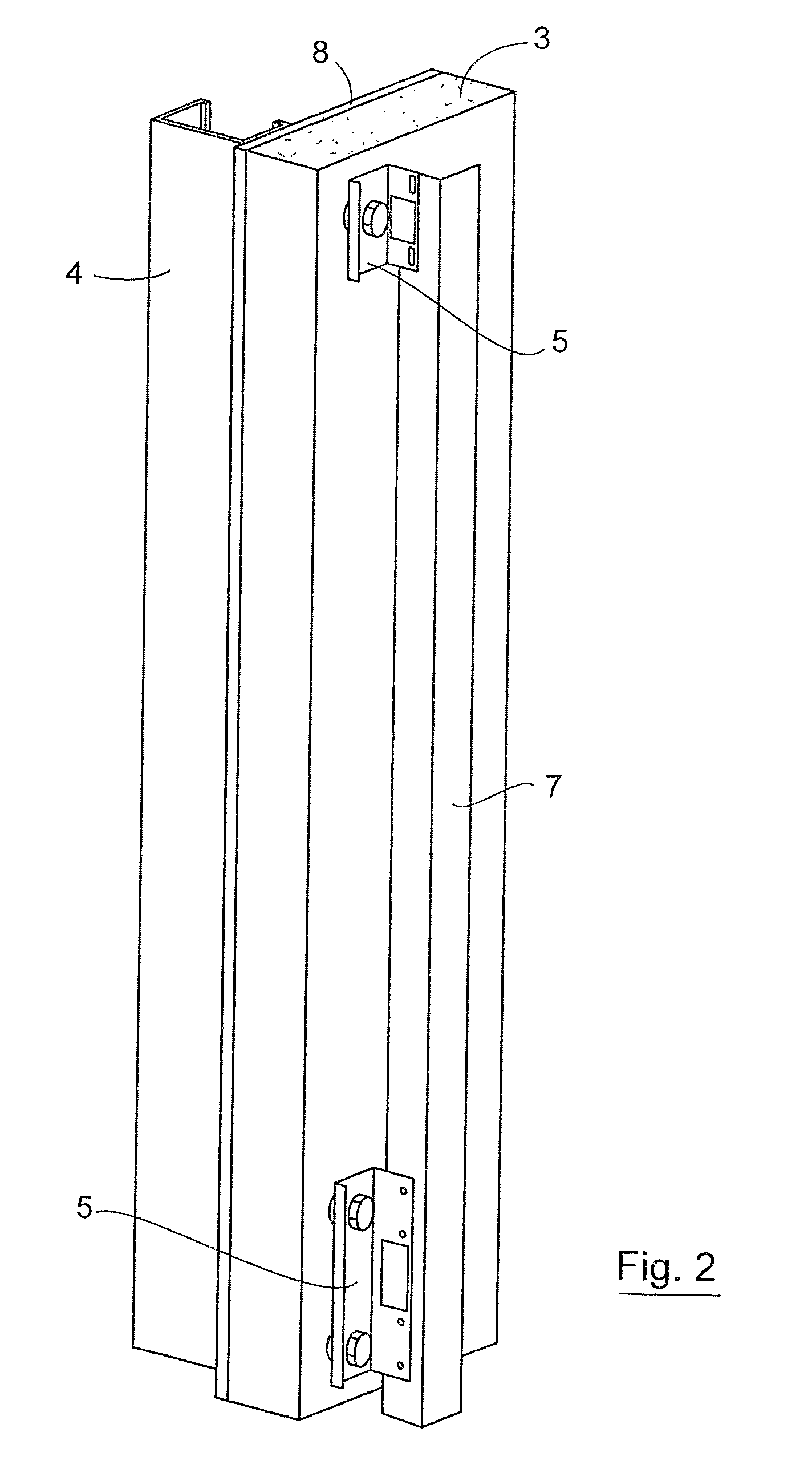
[0060]Referring to the drawings and initially to FIGS. 1 to 6 there is illustrated a support system for mounting building facade elements 1 to a framework 2. An insulation body 3 is attached to the framework 2 and a plurality of brackets 5 are used to interconnect the framework 2 and the facade elements 2. A plurality of spacer elements or fixings 6 are used to mount the brackets 5 to the support framework 2. In-line brackets 5 are interconnected by a support element 7. A sheathing board 8 may be interposed between the frame 2 and the insulation body 3. The brackets 5 may have slotted fixing holes 9 to facilitate thermal expansion

[0061]The fixing 6 comprises a generally cylindrical spacer section 10 and a frame fixing element 11 in the form of a screw for fixing to a frame 2. The spacer section 10 also defines a receiver 12 for reception of a bracket fixing 13 which may be in the form of a bolt. The spacer section 10 may be screw threaded at 14 to receive a correspondingly threaded ...


PUM


Abstract

A support system for mounting building facade elements 1 to a framework 2 comprises a plurality of spacer elements or fixings 6. An insulation body is attached to the framework 2 and a plurality of brackets 5 are used to interconnect the framework 2 and the facade elements 1. The fixings 6 are used to mount the brackets 5 to the support framework 2. In-line brackets 5 are interconnected by a linear support element 7. Loading L is applied downwardly on the brackets 5 due to gravity. The load is transmitted to a screw 11 which acts in a shear direction S. Rotational moments M1, M2 are resisted by the bracket connection element 7.

Description

[0001]The invention relates to a support system for an exterior cladding system. In particular, the invention relates to a support for a rainscreen system.[0002]Generally, a cladding or rainscreen is applied to a building frame. In one known system, a rainscreen in the form of a facade panel or board and its supports is attached to a building frame by means of a number of brackets. The purpose of the brackets is to carry the load from the facade. The load can be due to the weight of the panel and / or wind pressure. In one arrangement the brackets are inserted through pre cut holes in the insulation layer. Screws are used to fix the brackets to the substrate beneath. The length of the brackets is varied, depending on the insulation thickness and cavity required. After fitting the pre-cut holes are refilled and sealed.[0003]There are a number of problems with conventional systems. The brackets provide a heat conductor which may adversely affect the thermal performance. The systems are ...

Claims


Application Information

Patent Timeline
IPC IPC(8): E04C2/38F16B25/10
CPCE04F13/0803E04F13/0805
Inventor STEVENS, MARK VICTORGARNER, LEO
Owner KINGSPAN HLDG (IRL) LTD
Learn More