Device and method for controlling a satellite tracking antenna

a satellite tracking and antenna technology, applied in the direction of antennas, antenna details, antenna adaptation in movable bodies, etc., can solve the problems of system failure, system failure, and inability to meet, so as to improve the ability to make, improve the stabilising performance of the device, and improve the effect of the ability to mak

Active Publication Date: 2010-08-12
SAAB AB
View PDF7 Cites 26 Cited by
  • Summary
  • Abstract
  • Description
  • Claims
  • Application Information

AI Technical Summary

Benefits of technology

[0022]This improves the ability to both transmit and receive information. The additional gyro according to the invention improves the stabilising performance of the device. The additional gyro according to the invention improves the ability to make sure that the angular velocity of the antenna pointing vector is small in the inertial frame, thus improving ability to maintain a correct pointing direction in the global coordinate system defined by north, west and up. The additional gyro is thus controls quick changes on the pointing direction of the antenna.
[0023]According to an embodiment the method further comprises the step of imparting a rotational motion to a transceiver head of the antenna about a polarization axis orthogonal to the tilt axis, wherein the polarisation axis is conne

Problems solved by technology

However, at an elevation angle above 45° the response between roll motion and required compensation in azimuth and elevation direction becomes too large.
However, at elevation angles above 45° involving roll motions such a three axis system does not work due to the above menti

Method used


Image

  • Device and method for controlling a satellite tracking antenna
  • Device and method for controlling a satellite tracking antenna
  • Device and method for controlling a satellite tracking antenna

Examples


first embodiment

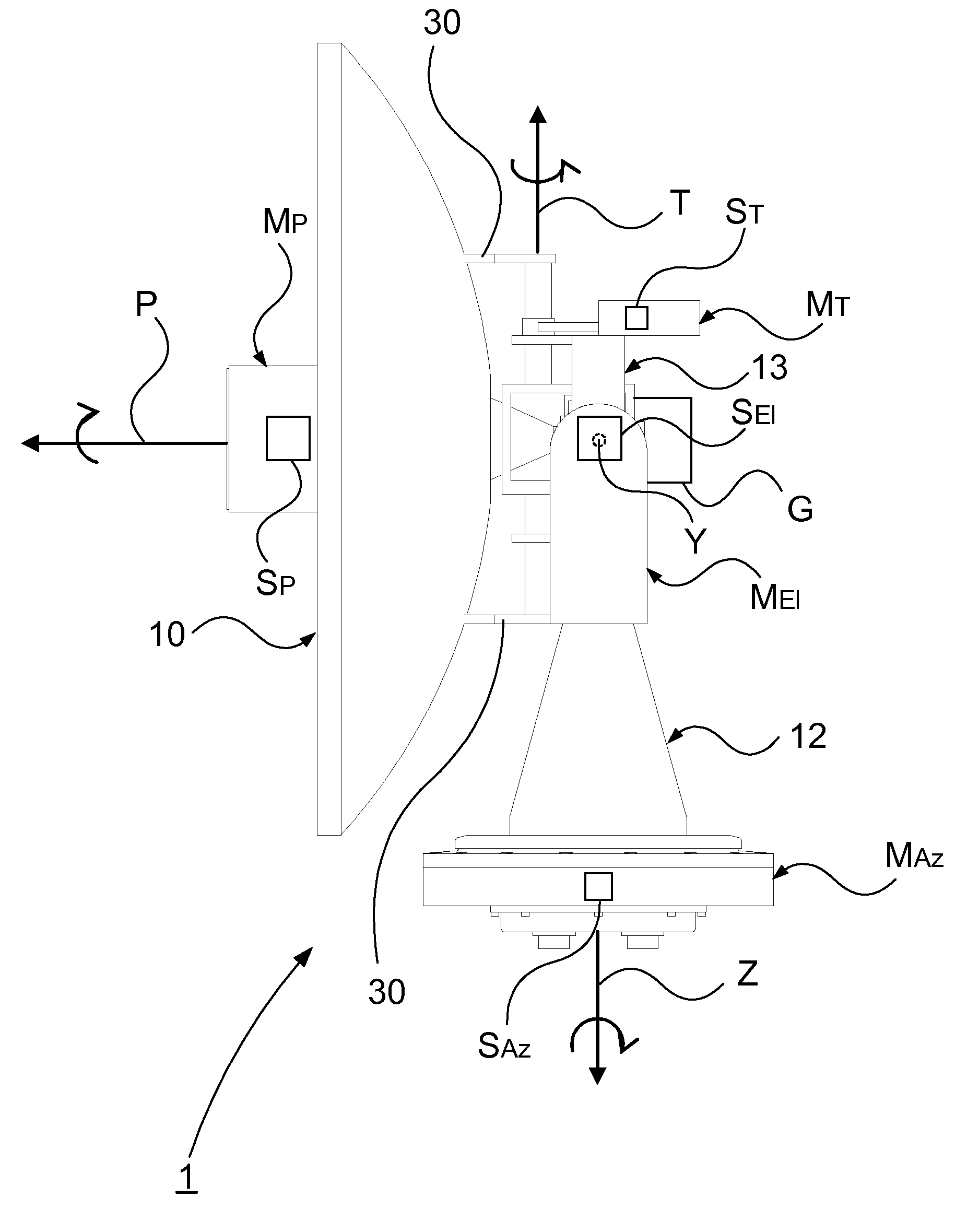
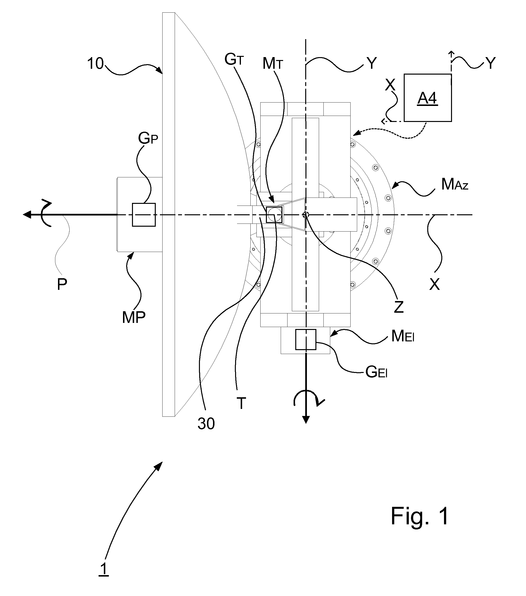
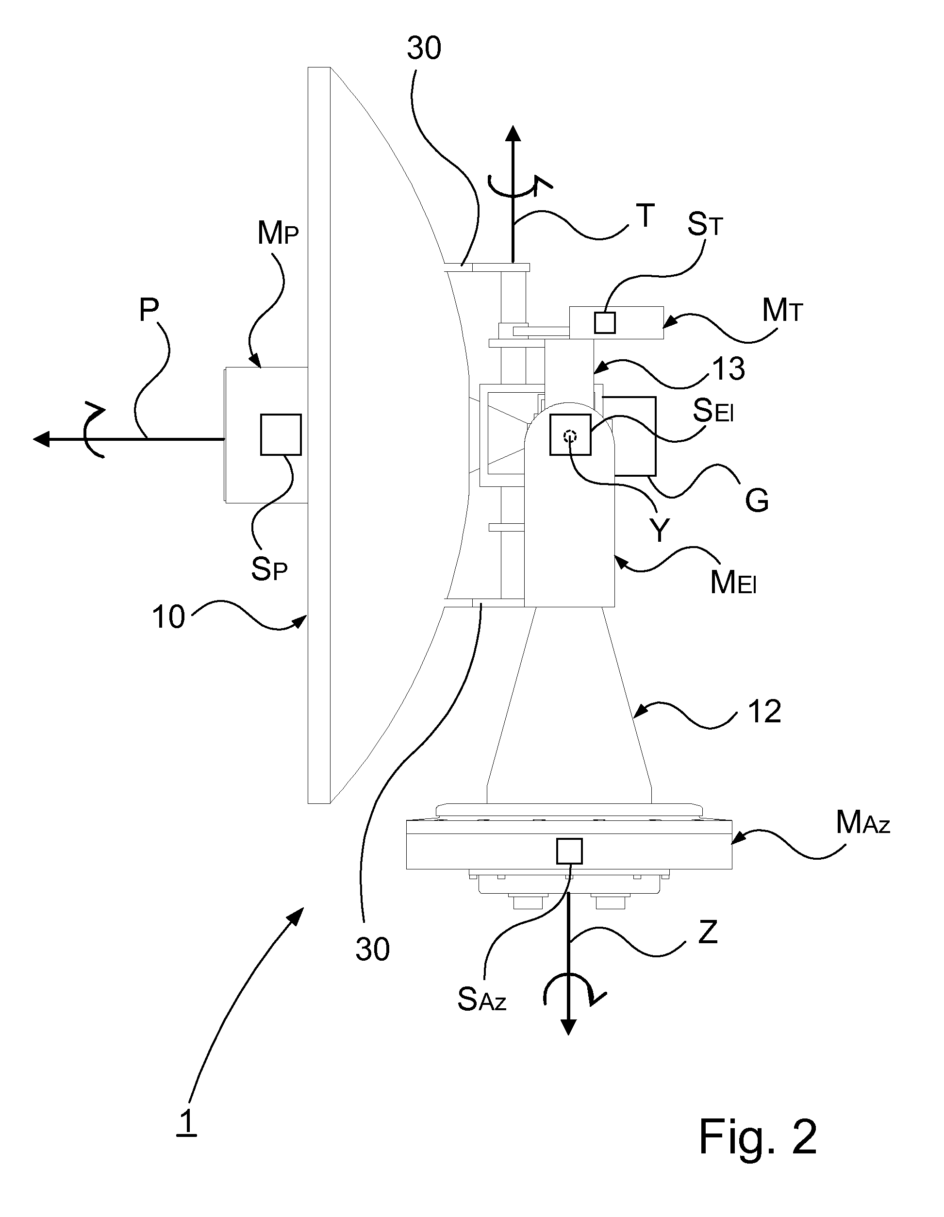
[0045]FIG. 1-3 show different views of a device 1 for controlling a satellite tracking antenna 10 according to the present invention. The azimuth axis drive means MAz constitutes a base. The base is arranged to support a support member 12 having a U-shaped configuration, said member being fixed to the base and having legs projecting upwardly from the base.

[0046]The support member 12 is arranged to carry a frame member 13 at an upper portion of said support member by means of the elevation axis Y, the frame member being rotatably arranged about the elevation axis Y. The elevation axis Y is thus located at a certain level above the base. The frame member 12 is connected to the antenna 10 via the tilt axis T. The tilt axis T is connected to the antenna 10 via a first and a second connection member 30, said members 30 being fixed to the antenna and connected to the tilt axis T such that the antenna is rotated when the tilt axis is rotated. The azimuth axis drive means MAz is arranged to...

second embodiment

[0048]FIG. 4 shows schematically a plan view of a device 2 for controlling a satellite tracking antenna 10 according to the present invention. The azimuth axis drive means MAz constitutes a base. The azimuth axis drive means MAz is arranged to impart a rotational motion to the base about the azimuth axis Z. The device further comprises an extension 14 rotationally connected to the elevation axis Y. The tilt axis T is connected to the elevation axis Y by means of said extension 14. The elevation axis drive means comprises a first and a second elevation motor MEl arranged to impart a rotational motion to the extension 14, and thus the antenna 10, about the elevation axis Y, the first and second motor being connected to the elevation axis Y at each side of the elevation axis, respectively. Alternatively the elevation axis drive means comprises a single motor arranged to impart a rotational motion to the elevation arm 14 about the elevation axis, the motor being connected to a side of t...

third embodiment

[0050]FIG. 5 shows schematically a plan view of a device 3 according to the present invention. The azimuth axis drive means MAz constitutes a base, and is arranged to impart a rotational motion to the base about the azimuth axis. The elevation axis drive means MEl is arranged to impart a rotational motion about the elevation axis Y. The device further comprises an extension 15 connected to the elevation axis drive means MEl. The tilt axis T is connected to the elevation axis Y by means of said extension 15. The tilt axis T is directly associated with the antenna 10, such that the antenna is rotatable about the tilt axis T. The elevation axis drive means comprises an elevation motor MEl arranged to impart a rotational motion about the elevation axis Y, and thus to the antenna 10 via the extension 15.

[0051]In this embodiment the tilt axis drive means comprises a first and second tilt motor MT1, MT2. The first motor MT1 is arranged to drive a transmission means constituted by a first b...


PUM


Abstract

A device for controlling a satellite tracking antenna. An azimuth drive is configured to impart an azimuthal rotational motion to the antenna about an azimuth axis. An elevation axis drive is configured to impart a rotational motion to the antenna about an elevation axis orthogonal to the azimuth axis. A tilt axis drive is configured to impart a rotational motion to the antenna about a tilt axis. The tilt axis is connected to the elevation axis in such a way that the rotational freedom of motion of the antenna about the tilt axis is dependent on the elevation angle such that: at an elevation angle of 0° the rotational freedom of motion of the antenna about the tilt axis corresponds to the azimuthal rotational motion; at an increasing elevation angle the rotational freedom of motion about the antenna successively transcends into a roll rotation; and at an elevation angle of 90° the rotational freedom of motion of the antenna about the tilt axis corresponds to a roll rotation about a roll axis orthogonal to the azimuth axis and to the elevation axis. A control controls the operation of the azimuth axis drive, the elevation axis drive, and the tilt axis drive. The control includes a true north seeking gyro for tracking position, orientation, direction and speed of movement of the device. The control further includes an additional gyro comprising an elevation gyro axis arranged to sense the elevation movement and a tilt gyro axis arranged to sense the tilt movement, so as to minimize the angular velocity of the antenna pointing vector. A method for controlling a satellite tracking antenna, and a vessel including the device.

Description

TECHNICAL FIELD[0001]The present invention relates to a device for controlling a satellite tracking antenna according to the preamble of claim 1. The present invention further relates to a method according to the preamble of 11. The present invention further relates to a vehicle according to the preamble of claim 14.BACKGROUND[0002]In order to automatically track the position of a satellite, satellite receivers are installed in moving objects such as vehicles, ships or the like. A device comprises means for adjusting azimuth angle and elevation angle of the antenna such that the position of the satellite is automatically tracked without adjustment of the wave-receiving angle of the antenna.[0003]The use of such a two-axis system on a moving vehicle requires, in order to maintaining contact with the satellite, that the direction vector all the time is kept parallel. To accomplish this with such a two-axis system roll movements are compensated by means of an azimuth motor which impart...

Claims


Application Information

Patent Timeline
IPC IPC(8): H01Q3/08
CPCH01Q1/288H01Q19/12H01Q3/08H01Q1/34
Inventor HELLBERG, DANIEL
Owner SAAB AB
Why Eureka
Try Eureka