Multi-beam antenna with multi-device control unit

Active Publication Date: 2010-08-12
AMPHENOL CORP
View PDF6 Cites 47 Cited by
  • Summary
  • Abstract
  • Description
  • Claims
  • Application Information

AI Technical Summary

Benefits of technology

[0009]The present invention meets the need described above in a RET antenna with a multi-device control unit that is configured to be inserted into and removed from a receptacle in the antenna. The multi-device control unit works with one or more modular switching units, which are typically located inside the antenna enclosure, to control the motors and position sensors located in

Problems solved by technology

This design approach is expensive due to the cost of the external cable assemblies and the redundant electronic components used by multiple RET actuat

Method used


Image

  • Multi-beam antenna with multi-device control unit
  • Multi-beam antenna with multi-device control unit
  • Multi-beam antenna with multi-device control unit

Examples


Embodiment Construction

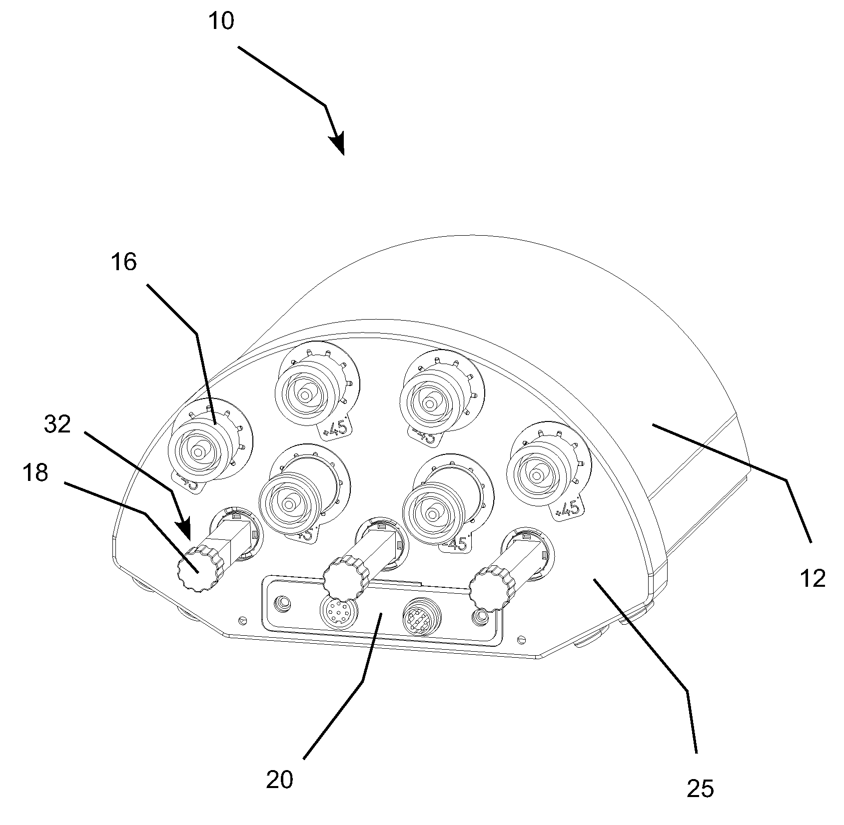
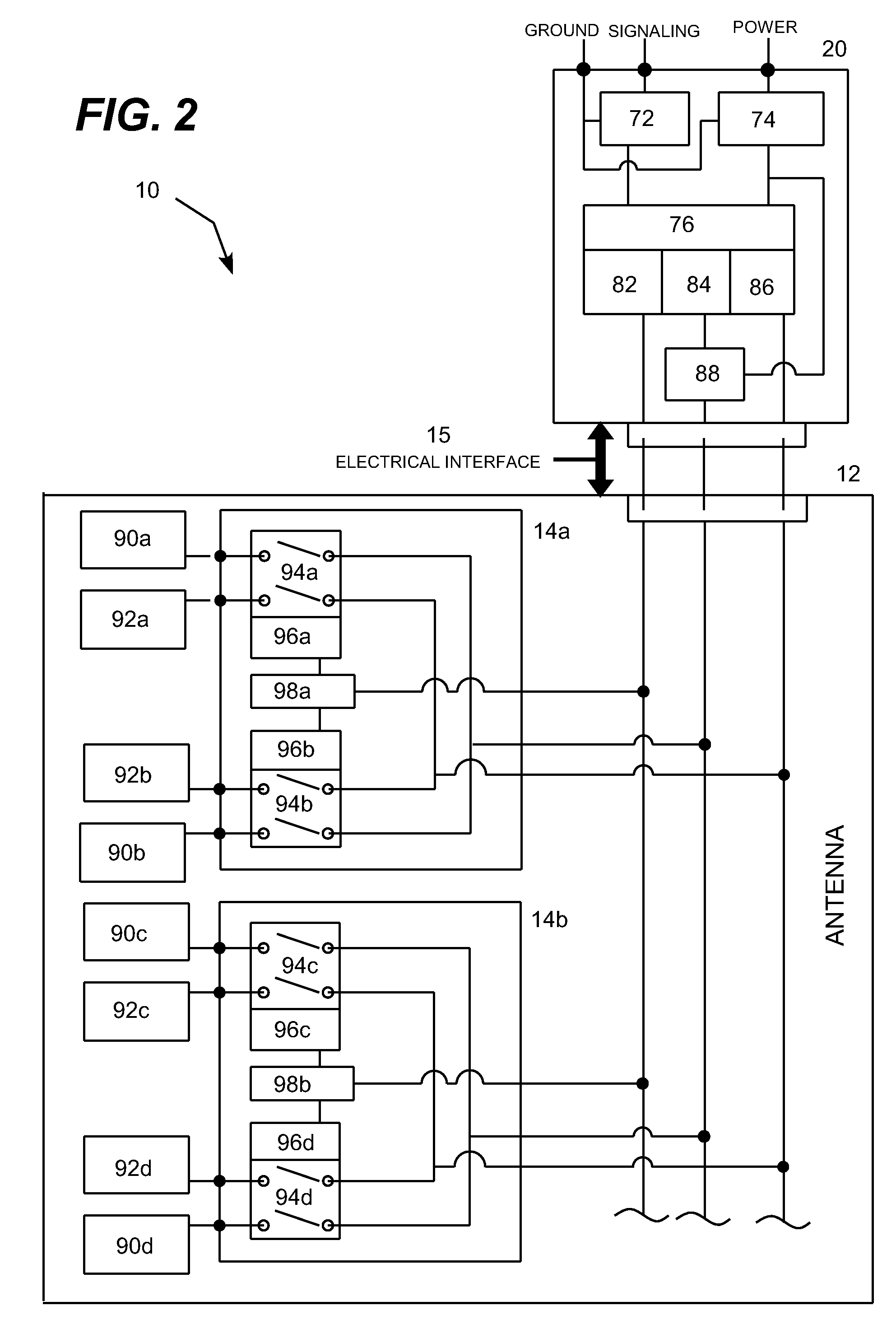
[0022]The present invention meets the need described above in a RET antenna with a multi-device control unit that can be inserted into and removed from a receptacle in the antenna. The multi-device control unit works with one or more modular switching units, which are typically located inside the antenna enclosure. The multi-device control unit works together with motors and position sensors located inside the antenna to allow a single controller located in the multi-device control unit to control multiple embedded electro-mechanical actuators, such as phase shifter control motors. This enables multiple motors to share a common control system located in the multi-device control unit, which greatly reduces the number of electronic components required for a multi-beam RET antenna.

[0023]The multi-device control unit typically includes one or more lightning protection circuits, communications circuits, motor controllers, power control circuits and motor position sensing circuits inside ...


PUM


Abstract

RET antenna with a modular switching unit and a multi-device control unit con figured to be inserted into and removed from a receptacle in the antenna. The multi-device control unit works together with motors and position sensors located inside the antenna to allow a single controller located in the multi-device control unit to control multiple embedded electro-mechanical actuators, such as phase shifter control motors. The multi-device control unit includes lightning protection circuits, communications circuits, a motor controller, power control circuits and a motor position sensing circuit inside a small housing. These components are shared between all motors inside the antenna through the modular switching unit, which allows a single set of components within the multi-device control unit to replace redundant components deployed in prior RET antennas.

Description

REFERENCE TO PRIORITY APPLICATIONS[0001]This application claims priority to commonly-owned U.S. Provisional Patent Application No. 60 / 027,687, which is incorporated herein by reference.TECHNICAL FIELD[0002]This invention relates to the field of cellular or mobile telephone base station antennas and, more particularly, relates to a remote electrical tilt (RET) base station antenna with a removable multi-device control unit that can be switched to remotely control more than one electro-mechanical actuator contained inside the antenna.BACKGROUND OF THE INVENTION[0003]Antennas with variable electrical tilt (VET) functionality are known in the art. These antennas, which are used in cellular networks, enable network operators to electrically tilt the elevation beam pointing direction of the antenna by manually rotating a knob or translating a shaft on the exterior of the antenna. The knob or shaft is linked to phase shifters inside the antenna that convert the mechanical rotation or trans...

Claims


Application Information

Patent Timeline
IPC IPC(8): H01Q3/00
CPCH01Q1/246H01Q21/08H01Q3/32
Inventor GIRARD, GREGORYSOULIE, FRANKPROTEAU, ERICPALLONE, ANTHONY
Owner AMPHENOL CORP
Why Eureka
Try Eureka