
Liquid ejection apparatus

Inactive Publication Date: 2010-08-12
SONY CORP
View PDF4 Cites 22 Cited by
  • Summary
  • Abstract
  • Description
  • Claims
  • Application Information

AI Technical Summary

Benefits of technology

[0015]Therefore, it is desirable to provide a liquid ejection apparatus in which switching can be performed between the printing state, the cleaning state, and the waiting state with a simple configuration, in which fouling due to the outflow of waste ink does not occur, and in which the ink ejection surface can be wiped thoroughly.
[0017]The above-described embodiment of the present invention includes the rotating moving table that is rotatable between the horizontal orientation and the vertical orientation relative to the portion of the liquid ejection head in which the nozzle row is formed, and movable in the horizontal direction relative to the portion of the liquid ejection head in which the nozzle row is formed; the head cap that is movable so as to come into contact with or become spaced from the portion in which the nozzle row is formed; and the interlocking means that interlocks the rotation and movement of the rotating moving table with the movement of the head cap. Therefore, physical interference between the rotating moving table and the head cap is avoided by using the interlocking means.
[0019]When the rotating moving table has been rotated to the horizontal orientation, the head cap is situated in a position spaced from the portion in which the nozzle row is formed. When the rotating moving table has been rotated to the vertical orientation and is not being moved in the horizontal direction, the head cap can come into contact with the portion in which the nozzle row is formed. Therefore, the head cap can be switched to the waiting state (capping) without interfering with the rotating moving table. Furthermore, since the capping is performed by moving the head cap, problems arising in the case where the head cap is rotated, such as the outflow of waste ink in the head cap and the twisting of the suction tube, can be avoided.
[0020]According to an embodiment of the present invention, switching can easily be performed between the printing state, the cleaning state and the waiting state for the liquid ejection head without interference between the rotating moving table and the head cap. Moreover, the portion in which the nozzle row is formed can be cleaned uniformly, and fouling due to the outflow of waste ink or the like can be prevented.

Problems solved by technology

As a result, upon switching to a non-capping state, the waste ink drops down and fouls the surroundings.
Moreover, the moisturizing liquid, which is provided to prevent drying, also tends to flow out.
Even if a liquid-absorbing member is provided and impregnated with the moisturizing liquid, it is difficult to hold the moisturizing liquid in the cap portion.
Moreover, in these techniques, a suction tube, which is provided to remove bubbles in the liquid ejection head and discharge waste ink accumulated in the cap portion, has a complicated piping structure.
However, the hollow supporting shaft has to be configured such that the connection between a movable part and a fixed part is rotatable and liquid-tight.
As a result, as compared to the case where wiping is performed while maintaining the optimum contact pressure by using horizontal movement, areas on the ink ejection surface often fail to be wiped and, moreover, the area that can be wiped is small.

Method used


Image

  • Liquid ejection apparatus
  • Liquid ejection apparatus
  • Liquid ejection apparatus

Examples


Embodiment Construction

[0035]An embodiment of the present invention is described below with reference to the drawings.

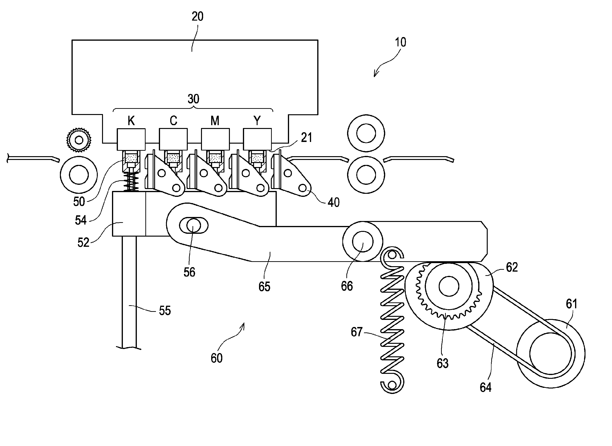
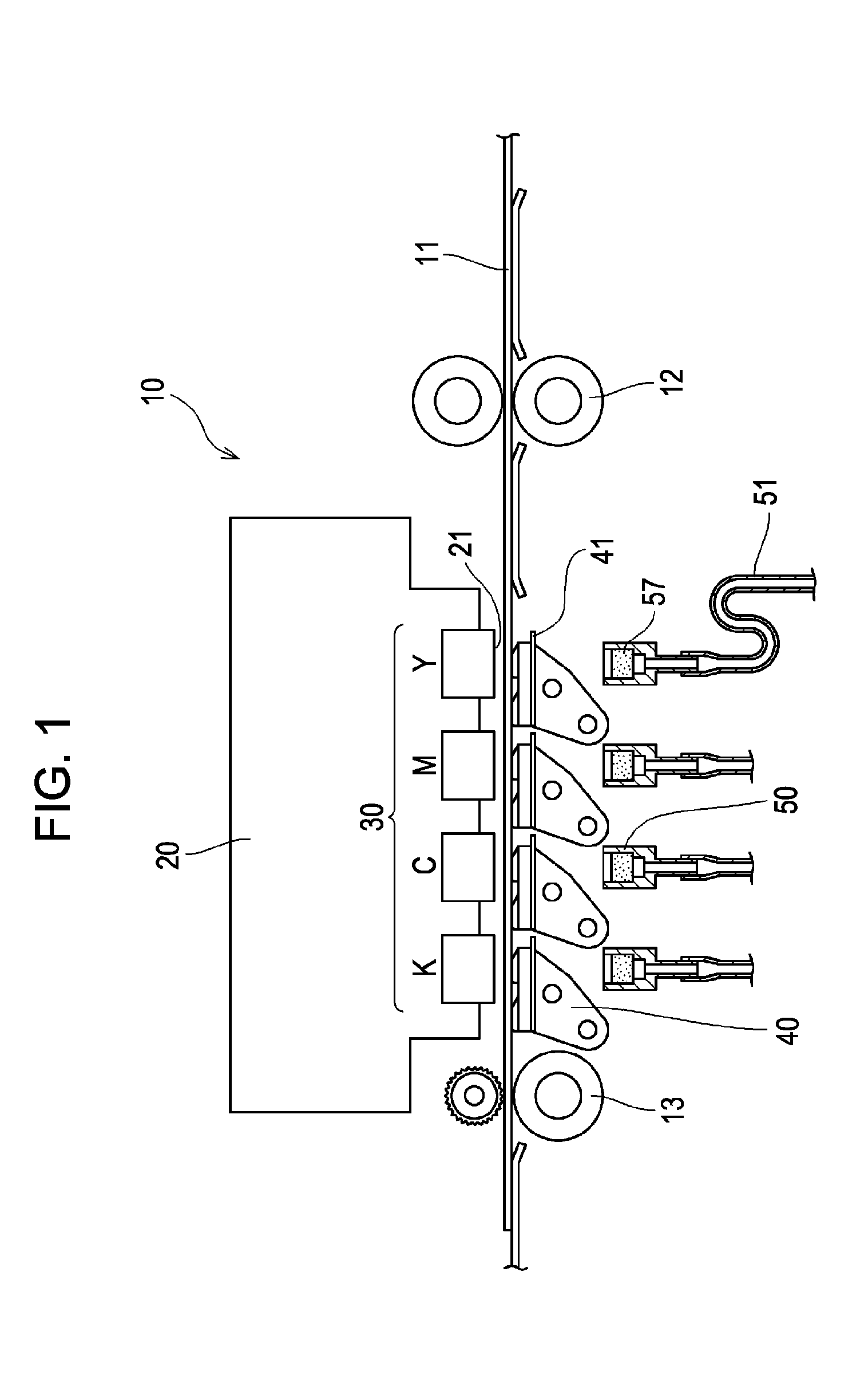
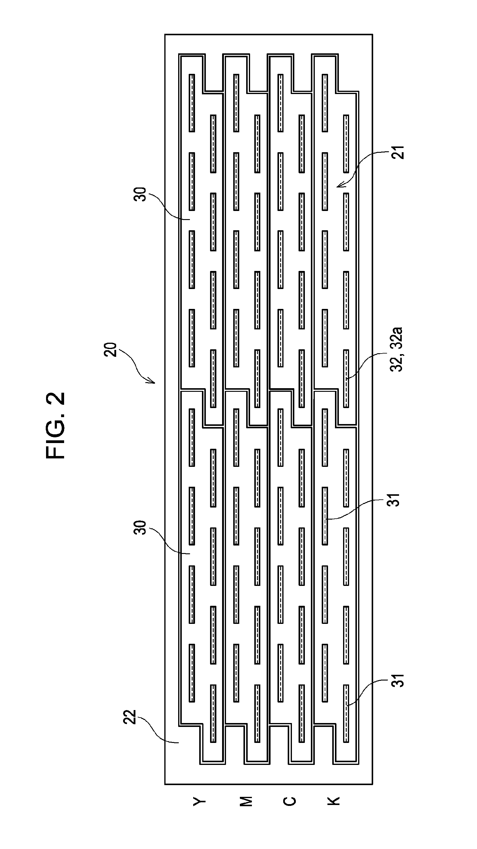
[0036]A liquid ejection apparatus of the following embodiment of the present invention is an ink jet printer 10 that ejects ink as a liquid. The ink jet printer 10 is a line-type ink jet printer, and has a line head 20 (liquid ejection head of an embodiment of the present invention) of a length corresponding to the width of printing (for example, A4 size). The line head 20 has formed therein nozzle rows 32a, each of which has a plurality of nozzles 32 that eject ink. The nozzles 32 are arranged in one direction at a predetermined pitch over a length corresponding to the width of a recording sheet 11 (target of ejection of an embodiment of the present invention) having the largest printable size. The nozzle rows 32a are formed in an ink ejection surface 21. The ink jet printer 10 is adapted for color printing, and the nozzle rows 32a are formed for each of the ink colors: yellow (Y), magent...


PUM


Abstract

A liquid ejection apparatus includes a rotating moving table that is rotatable between a horizontal orientation and a vertical orientation and movable in a horizontal direction; a head cap that is movable so as to come into contact with or become spaced from the liquid ejection surface; and an interlocking mechanism that interlocks the rotating moving table with the head cap. The rotating moving table has a platen portion on which a target of ejection of a liquid can be carried; and a cleaning portion that can clean the liquid ejection surface. When the rotating moving table has been rotated to the horizontal orientation, the head cap is situated in a position spaced from the liquid ejection surface. When the rotating moving table has been rotated to the vertical orientation and is not being moved in the horizontal direction, the head cap can come into contact with the liquid ejection surface.

Description

BACKGROUND OF THE INVENTION[0001]1. Field of the Invention[0002]The present invention relates to a liquid ejection apparatus in which switching can easily be performed from a printing state to a cleaning state or a waiting state for a liquid ejection head having formed therein a nozzle row that ejects a liquid.[0003]2. Description of the Related Art[0004]In a liquid ejection apparatus such as an ink jet printer, a liquid is ejected from a nozzle row formed in a liquid ejection head, and an image or the like is formed on a recording sheet. Therefore, if an image or the like is formed while an ink ejection surface of the liquid ejection head from which the liquid is ejected (the portion in which the nozzle row is formed) is dirty, or while a liquid, dirt or the like adheres to the surface, the quality of printing is degraded. Especially, in the case of a full-color ink jet printer, if an ink (a liquid) of a color different from that of another ink flows back through a nozzle into wher...

Claims


Application Information

Patent Timeline
IPC IPC(8): B41J2/165
CPCB41J2/16511B41J2/16585B41J2/16547
Inventor YAMAGUCHI, SHUNJI
Owner SONY CORP
Learn More