Equipment, method and use of the equipment in an audio system

a technology of audio system and equipment, applied in the direction of loudspeakers, transducer casings/cabinets/supports, microphones, etc., can solve the problems of poor attenuation of acoustic and mechanical vibrations, high cost and microphone specific support, interference with electroacoustic measurement and calibration, etc., to prevent the limiting of the measuring signal, reduce the level of the signal, and improve the signal-noise ratio

Inactive Publication Date: 2010-08-12
GENELEC
View PDF11 Cites 3 Cited by
  • Summary
  • Abstract
  • Description
  • Claims
  • Application Information

AI Technical Summary

Benefits of technology

[0027]Peak limiting of the measuring signal can be prevented by reducing the level of the signal. The signal-noise ratio can be improved by raising the level of the signal.

Problems solved by technology

A drawback of the state of the art is that, in the measuring system, the placing and firm installation of the microphone requires a microphone-specific support, which is generally very expensive and microphone specific.
In addition, even in expensive microphones the microphone support attenuates acoustic and mechanical vibrations poorly, which can significantly interfere with electroacoustic measurement and calibration.

Method used


Image

  • Equipment, method and use of the equipment in an audio system
  • Equipment, method and use of the equipment in an audio system
  • Equipment, method and use of the equipment in an audio system

Examples


Embodiment Construction

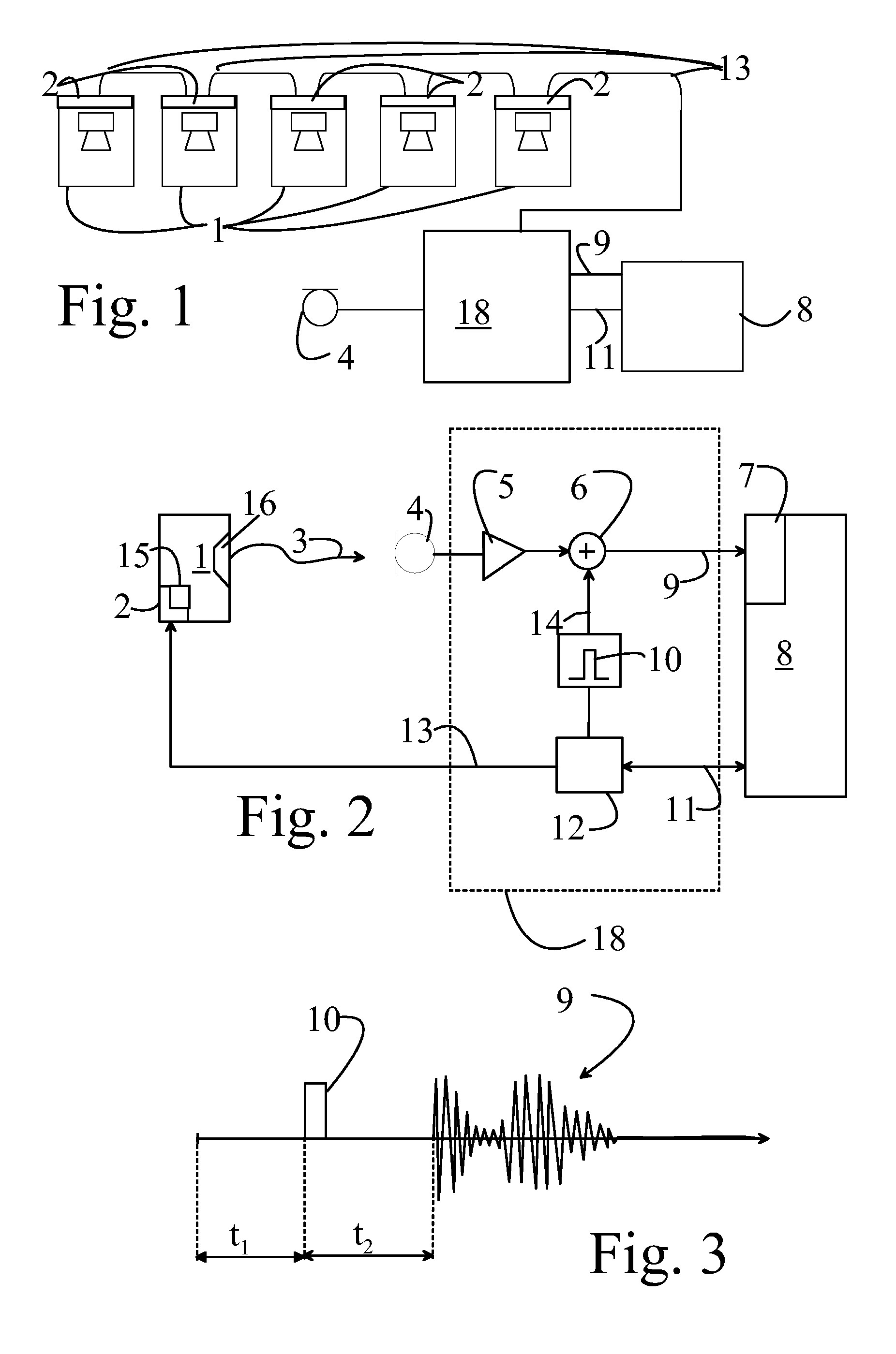
[0067]FIG. 1 shows the apparatus totality, in which loudspeakers 1 are connected to a computer 8 through a control network 13, by means of an interface device 18.

[0068]The interface device 18 contains a control-network controller 12 according to FIG. 2, a preamplifier 5 and an analog summer 6, to which an IO line 15 coming from the control-network controller, through which IO line a test signal 10 is transmitted to the summer, is connected.

[0069]FIG. 2 contains the same functions as FIG. 1, but only one loudspeaker 1 is shown, for reasons of clarity.

[0070]FIG. 2 shows the apparatus totality of the invention, in which the loudspeaker 1 produces an acoustic signal 3. For test purposes an acoustic signal 3 is created from an electrical calibration signal formed by the generator 15 of the control unit 2 of the loudspeaker itself. The control unit 2 typically contains an amplifier thus making the loudspeaker (1) an active loudspeaker. The test signal is preferably a sinusoidal scanning s...


PUM


Abstract

A method and means for a sound-reproduction system. The means include a first opening arrangement for a microphone, and a second opening arrangement for a microphone stand, formed in an essentially planar elastic material.

Description

BACKGROUND OF THE INVENTION[0001]1. Field of the Invention[0002]The present invention relates to a means for a sound-reproduction system.[0003]The invention also relates to a method in a sound-reproduction equipment.[0004]2. Brief Discussion of the Related Art[0005]According to the prior art, calibration methods are known, in which a test signal is fed to a loudspeaker. The response to the test signal is measured using a measuring system and the frequency response of the system is adjusted to be as even as possible using an equalizer.[0006]A drawback of the state of the art is that, in the measuring system, the placing and firm installation of the microphone requires a microphone-specific support, which is generally very expensive and microphone specific. In addition, even in expensive microphones the microphone support attenuates acoustic and mechanical vibrations poorly, which can significantly interfere with electroacoustic measurement and calibration.[0007]The invention is inten...

Claims


Application Information

Patent Timeline
Patent Type & Authority Applications(United States)
IPC IPC(8): H04R1/08H04R29/00
CPCH04R1/08H04S7/301H04R2201/028
Inventor MAKINEN, JARIMAKIVIRTA, AKITIKKANEN, JUSSIURHONEN, JUHA
Owner GENELEC
Why Eureka
Try Eureka