Monitoring Apparatus

a technology of monitoring apparatus and monitoring device, which is applied in the field of monitoring apparatus, can solve problems such as adversely affecting image processing, and achieve the effect of stable monitoring result and suppressing the signal level of image processing

Inactive Publication Date: 2021-07-01
MITSUBISHI ELECTRIC CORP
View PDF0 Cites 5 Cited by
  • Summary
  • Abstract
  • Description
  • Claims
  • Application Information

AI Technical Summary

Benefits of technology

[0008]According to the disclosure, the directions of the polarization axes of the two polarization filters can be varied and hence errors in a relative angle due to errors in manufacturing of the polarization filters or accuracy in assembly at the time of manufacturing can be adjusted. Therefore, lowering in signal level for image processing can be suppressed and a stable result of monitoring is obtained.

Problems solved by technology

It has been known in connection with a near infrared image pick-up apparatus that a virtual image is created in a camera image due to reflection of light by presence of a glossy surface of a subject or presence of glass, which adversely affects image processing.

Method used


Image

  • Monitoring Apparatus
  • Monitoring Apparatus
  • Monitoring Apparatus

Examples


first embodiment

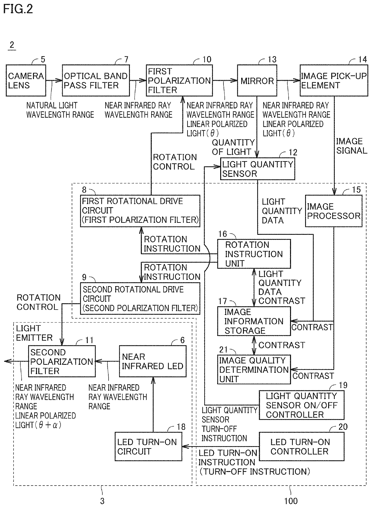
[0033]FIG. 4 is a flowchart for illustrating processing performed by the controller of the monitoring apparatus in a first embodiment. Controller 100 in FIG. 2 performs processing for removing a linear polarization component in a wavelength range of near infrared rays, of a virtual image created by reflection or scattering of sunlight in accordance with the flowchart in FIG. 4.

[0034]In steps S101 to S103, controller 100 determines an angle of rotation θ of polarization filter 10 on the camera side so as to minimize a quantity of light that enters the camera by reflection or scattering of sunlight initially with the LED being turned off. Thereafter, in steps S104 to S107, a relative angle α between two polarization filters is finely adjusted to obtain an image high in contrast with all LEDs being turned on.

[0035]Initially, in order to set polarization filter 10 on the camera side, controller 100 turns on the light quantity sensor in step S101. Then, in step S102, controller 100 contr...

second embodiment

[0045]Though a method of suppressing a virtual image by using light quantity sensor 12 is shown in the first embodiment, limitation thereto is not intended. A virtual image may also be suppressed only based on contrast of an image without using a light quantity sensor, as in a second embodiment described below.

[0046]In the second embodiment, relative angle a between first polarization filter 10 and second polarization filter 11 is initially set to 90°, angle of rotation θ at which a minimum value of unnecessary light is achieved is searched for, and relative angle α is finely adjusted based on contrast of an image after angle θ is determined. In the second embodiment, an effect of decrease in time period until completion of adjustment of an angle and an effect of obviating mirror 13 and light quantity sensor 12 are obtained.

[0047]FIG. 5 is a flowchart for illustrating processing performed by the controller of the monitoring apparatus in the second embodiment.

[0048]Referring to FIGS....

third embodiment

[0059]Though a method of suppressing a virtual image is shown in the first and second embodiments, limitation thereto is not intended. A specific approach to decrease in time period for adjustment of an angle will be described in a third embodiment.

[0060]A normal near infrared LED emits light without polarization. LEDs are individually different in angle at which intensity of light that can pass through a polarization filter is maximized. Therefore, depending on accuracy in assembly at the time of manufacturing and a lot of LEDs, intensity of light that can pass through the polarization filter is disadvantageously lowered and a signal level for image processing is lowered. In order to solve this problem, in the third embodiment, a relative angle between first polarization filter 10 and second polarization filter 11 is set to 0°, an angle of rotation β at which a quantity of light in accordance with a characteristic of an individual LED is maximized with the LED being turned on is fo...


PUM

PropertyMeasurementUnit
angleaaaaaaaaaa
angleaaaaaaaaaa
anglesaaaaaaaaaa

Abstract

A monitoring apparatus has a rotatable first polarization filter and a rotational drive circuit in an image pick-up element and has a second polarization filter and a rotational drive circuit on a light emission side of a near infrared LED. An angle of a polarization axis of the polarization filter is each independently adjustable. In order to lessen influence by sunlight or scattering, the polarization filter on a lens side is rotated to minimize output from a light quantity sensor while the near infrared LED is turned off. Optical noise is thus lowered. The polarization filter on an LED side is rotated to maximize contrast. Thus, a virtual image of a camera image due to reflection and scattering of light is lessened, quality of an image signal is improved, and a stable image signal is obtained. Thus, erroneous sensing in image processing can be lessened.

Description

TECHNICAL FIELD[0001]The disclosure relates to a monitoring apparatus and particularly to a monitoring apparatus configured to accurately pick up an image of an object to be recognized by preventing in an image, a virtual image caused by reflection or scattering of light.BACKGROUND ART[0002]A monitoring apparatus senses doze or inattentiveness of a driver by using a near infrared image pick-up apparatus and image processing. It has been known in connection with a near infrared image pick-up apparatus that a virtual image is created in a camera image due to reflection of light by presence of a glossy surface of a subject or presence of glass, which adversely affects image processing.[0003]A technique disclosed in Japanese Patent Laying-Open No. 2008-61211 (PTL 1) addresses a virtual image by providing a polarizing plate between near infrared rays and a subject and between the subject and a camera for preventing the virtual image.CITATION LISTPatent Literature[0004]PTL 1: Japanese Pat...

Claims


Application Information

Patent Timeline
Patent Type & Authority Applications(United States)
IPC IPC(8): G02B27/00G02B27/28H04N7/18H04N5/225H04N5/235
CPCG02B27/0018G02B27/281H04N7/18H04N5/2351H04N5/2254H04N5/2256H04N5/22521H04N7/183H04N5/33H04N23/56H04N23/55H04N23/60H04N23/52H04N23/71
Inventor KAWASAKI, SUMITOSHI
Owner MITSUBISHI ELECTRIC CORP
Why Eureka
Try Eureka