Fixing device and image forming apparatus incorporating same

Active Publication Date: 2010-08-12
RICOH KK
View PDF56 Cites 196 Cited by
  • Summary
  • Abstract
  • Description
  • Claims
  • Application Information

AI Technical Summary

Benefits of technology

[0013]The fixed member includes a body, a low-friction sheet member, and at least one plate spring. The body opposes the nip portion. The low-friction sheet member is wrapped around the body of the fixed member in a sliding direction in which the belt member slides over the fixed mem

Problems solved by technology

However, over time, as an inner circumferential surface of the belt member slides over the heater, the heater and the belt member may experience wear due to friction generated therebetween.
Further, substantial resistance between the belt member and the heater, again due to friction generated therebetween, may require great driving torque, which may in turn pose a risk of generating faulty toner images due to slippage of the belt member, damage to drive gear teeth, or both.
As such, the low-friction sheet member may not adhere to the pressing pad sufficiently, and ther

Method used


Image

  • Fixing device and image forming apparatus incorporating same
  • Fixing device and image forming apparatus incorporating same
  • Fixing device and image forming apparatus incorporating same

Examples


Embodiment Construction

[0034]In describing exemplary embodiments illustrated in the drawings, specific terminology is employed for the sake of clarity. However, the disclosure of this specification is not intended to be limited to the specific terminology so selected and it is to be understood that each specific element includes all technical equivalents that operate in a similar manner.

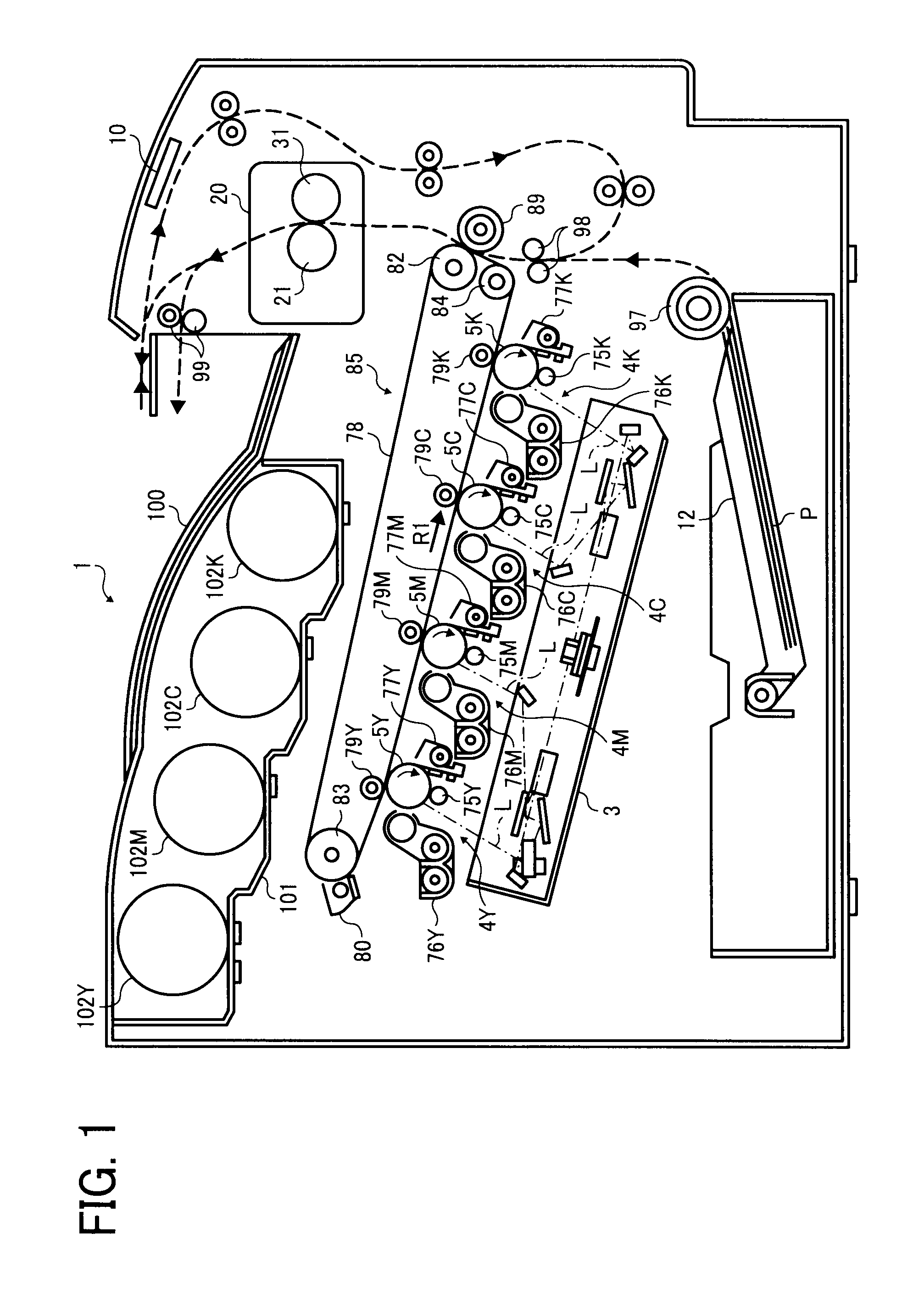
[0035]Referring now to the drawings, wherein like reference numerals designate identical or corresponding parts throughout the several views, in particular to FIG. 1, an image forming apparatus 1 according to an exemplary embodiment of the present invention is explained.

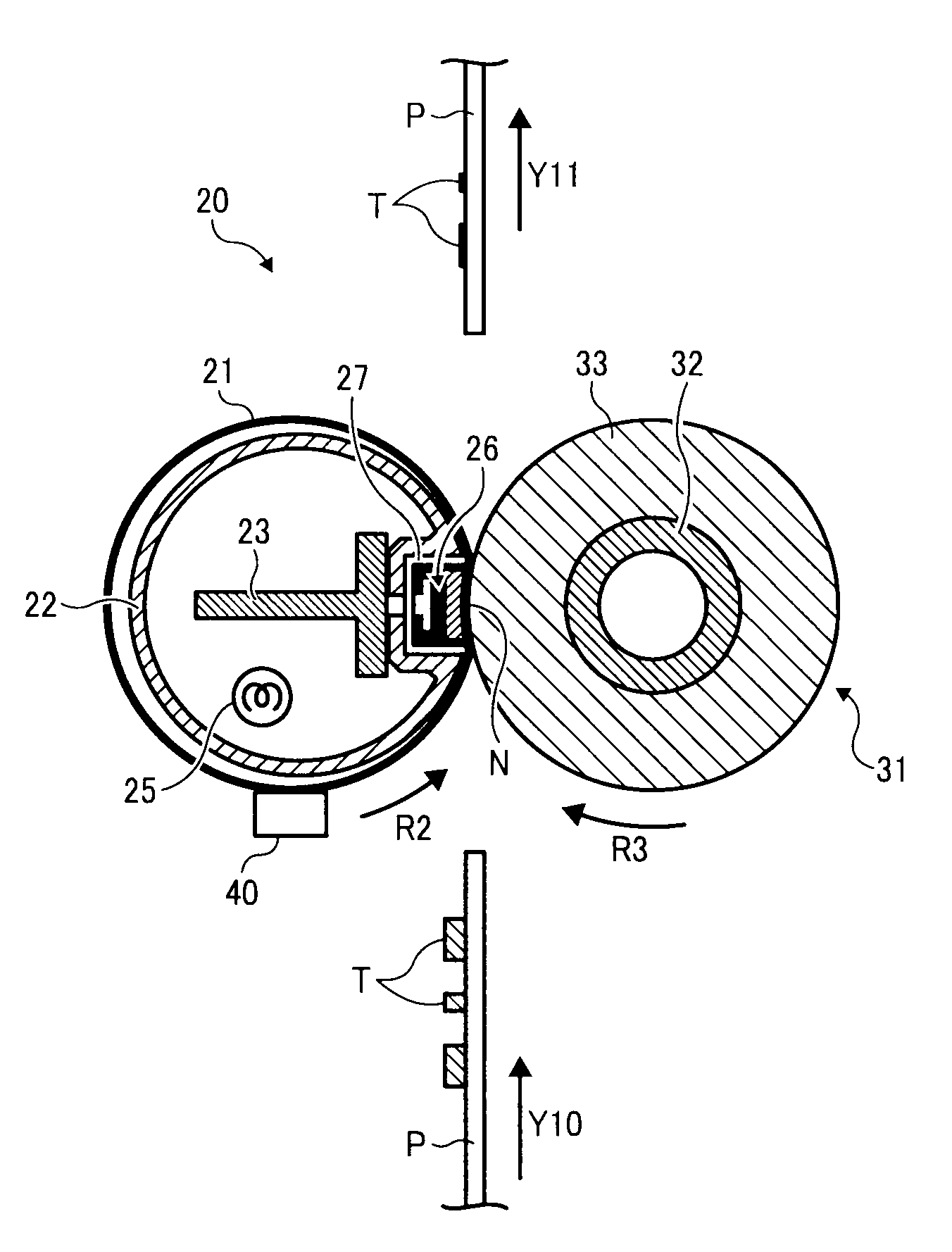
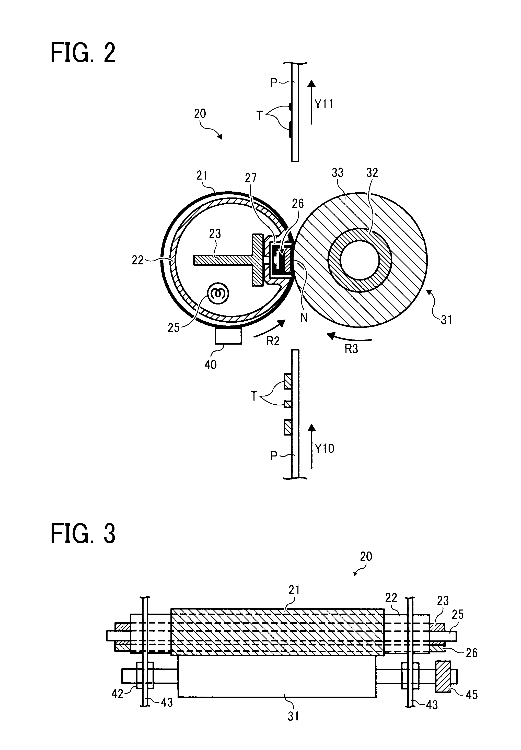
[0036]FIG. 1 is a schematic view of the image forming apparatus 1. As illustrated in FIG. 1, the image forming apparatus 1 includes an exposure device 3, image forming devices 4Y, 4M, 4C, and 4K, a controller 10, a paper tray 12, a fixing device 20, an intermediate transfer unit 85, a second transfer roller 89, a feed roller 97, a registration roller pair 9...


PUM


Abstract

In a fixing device, a fixed member is provided inside a loop formed by a belt member, and is pressed against a rotary member via the belt member to form a nip portion between the rotary member and the belt member through which a recording medium bearing a toner image passes. In the fixed member, a low-friction sheet member is wrapped around a body in a sliding direction of the belt member in which the belt member slides over the fixed member in such a manner that the low-friction sheet member covers a surface of the body opposing the nip portion. At least one plate spring presses the low-friction sheet member against the body to apply a predetermined tension to the low-friction sheet member.

Description

CROSS-REFERENCE TO RELATED APPLICATION[0001]The present application is based on and claims priority to Japanese Patent Application No. 2009-027586, filed on Feb. 9, 2009, in the Japan Patent Office, which is hereby incorporated herein by reference in its entirety.BACKGROUND OF THE INVENTION[0002]1. Field of the Invention[0003]Exemplary aspects of the present invention relate to a fixing device and an image forming apparatus, and more particularly, to a fixing device for fixing a toner image on a recording medium and an image forming apparatus including the fixing device.[0004]2. Description of the Related Art[0005]Related-art image foaming apparatuses, such as copiers, facsimile machines, printers, or multifunction printers having at least one of copying, printing, scanning, and facsimile functions, typically form an image on a recording medium (e.g., a transfer sheet) according to image data. Thus, for example, a charger uniformly charges a surface of an image carrier; an optical w...

Claims


Application Information

Patent Timeline
IPC IPC(8): G03G15/20
CPCG03G2215/2035G03G15/2064
Inventor SHINSHI, AKIRAYOSHINAGA, HIROSHIHASEGAWA, KENICHI
Owner RICOH KK
Why Eureka
Try Eureka