Turning motion assistance device for electric vehicle

a technology of motion assistance and electric vehicles, which is applied in the direction of steering initiation, instruments, vessel construction, etc., can solve the problems of easy wear of tires, obtain suppression effect against steering wheel tire wear, etc., and achieve the effect of reducing tire wear of the vehicle, suppressing the increase in the wheel slip angle of the steered wheels, and reducing the wear of tires

Active Publication Date: 2010-08-12
NIHON KENKI CO LTD
View PDF3 Cites 27 Cited by
  • Summary
  • Abstract
  • Description
  • Claims
  • Application Information

AI Technical Summary

Benefits of technology

[0007]An object of the present invention is to provide a turning motion assistance device for an electric vehicle, adapted to effectively reduce tire wear of the vehicle while at the same time ensuring appropriate turning response.
[0009]According to the present invention, increases in the wheel slip angle of the steered wheels can be suppressed, which in turn enables tire wear of the vehicle to be reduced while at the same time ensuring appropriate turning response.

Problems solved by technology

There has been the problem, however, that under the transient state of the turn, tires, in particular, easily become worn since a significant yawing moment is required and since driving wheels also increase in wheel slip angle.
Even if turning characteristics are expected to improve, therefore, it has been difficult, by using this conventional technique, to obtain a suppression effect against steering-wheel tire wear.

Method used


Image

  • Turning motion assistance device for electric vehicle
  • Turning motion assistance device for electric vehicle
  • Turning motion assistance device for electric vehicle

Examples


first embodiment

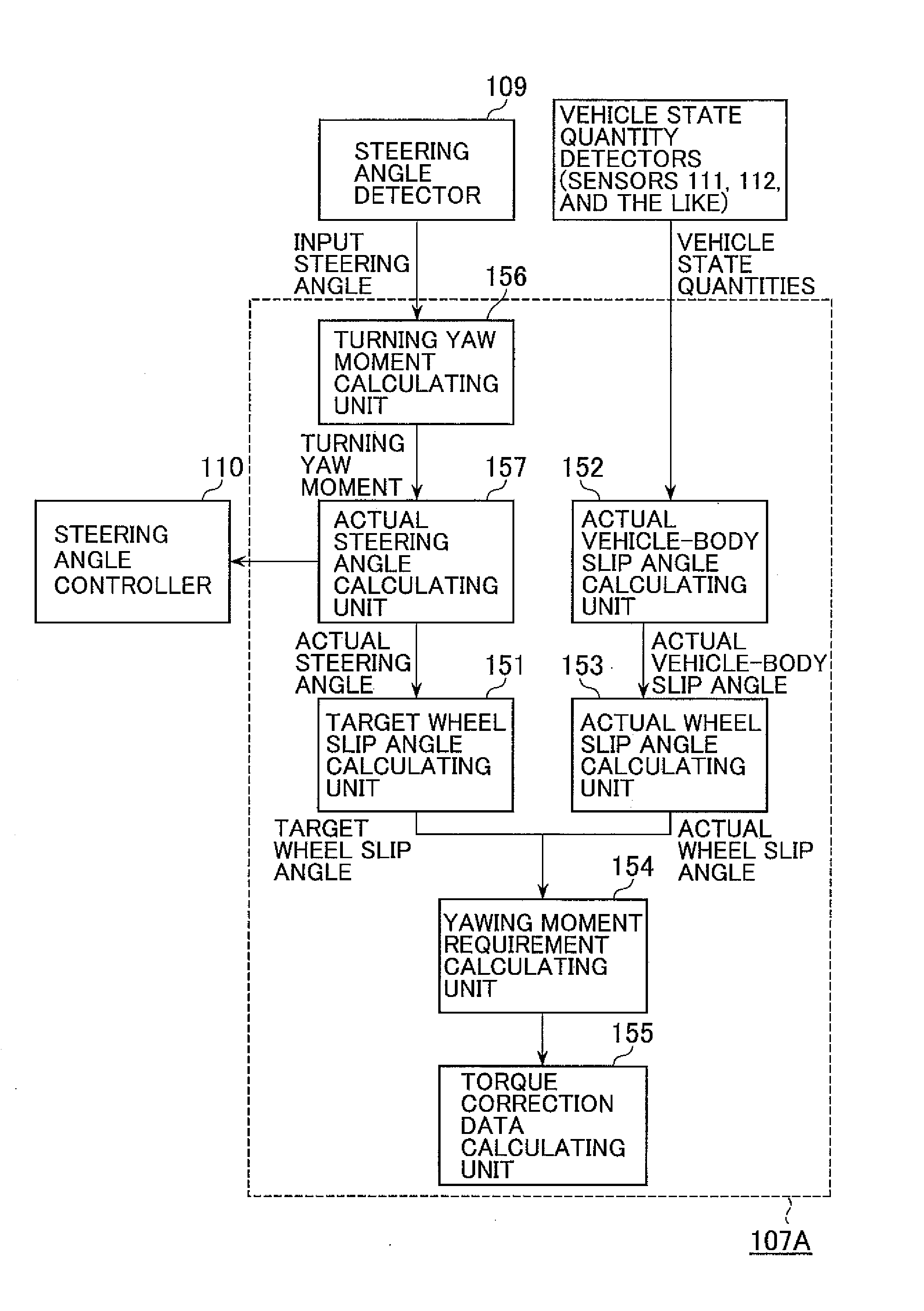
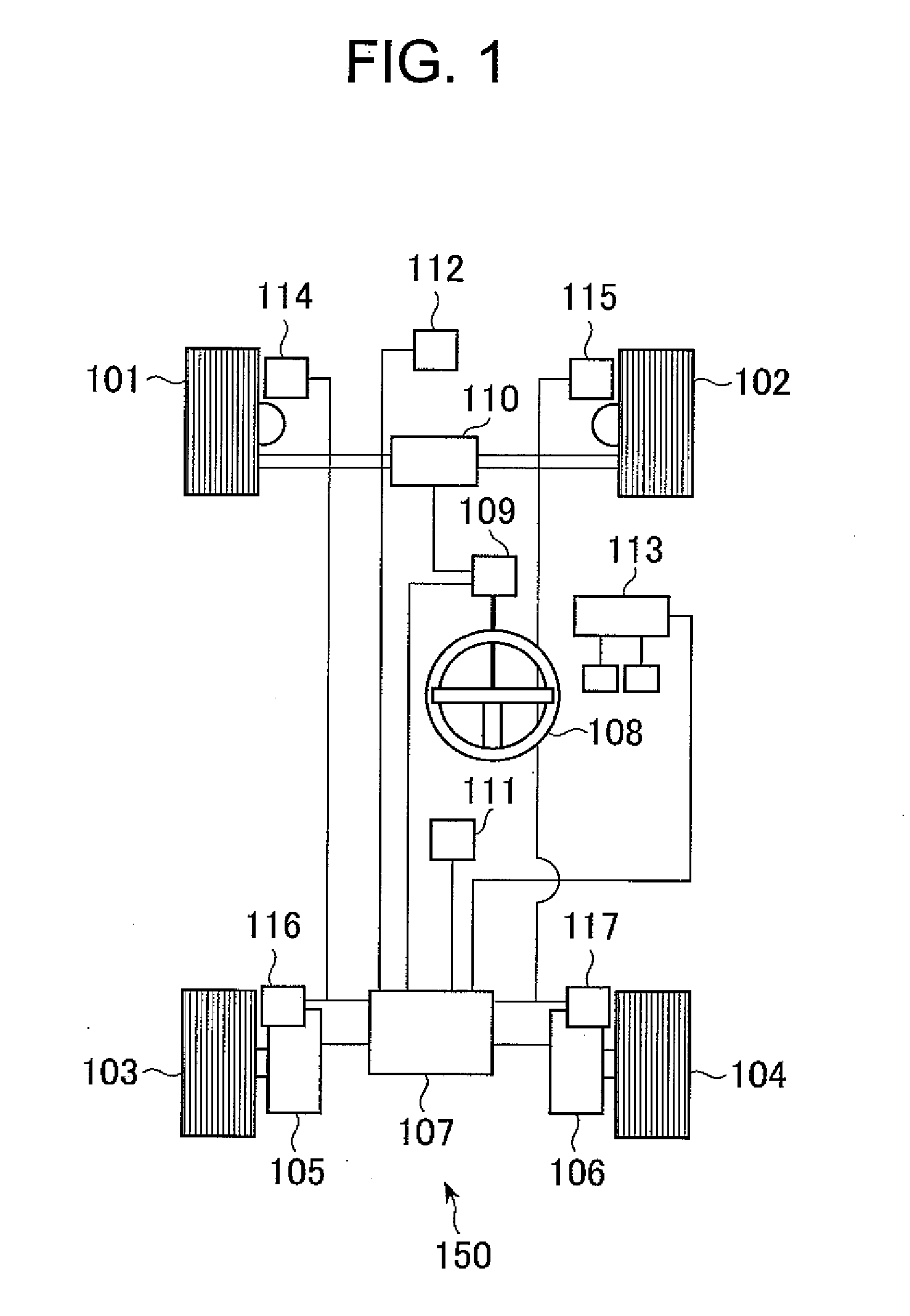
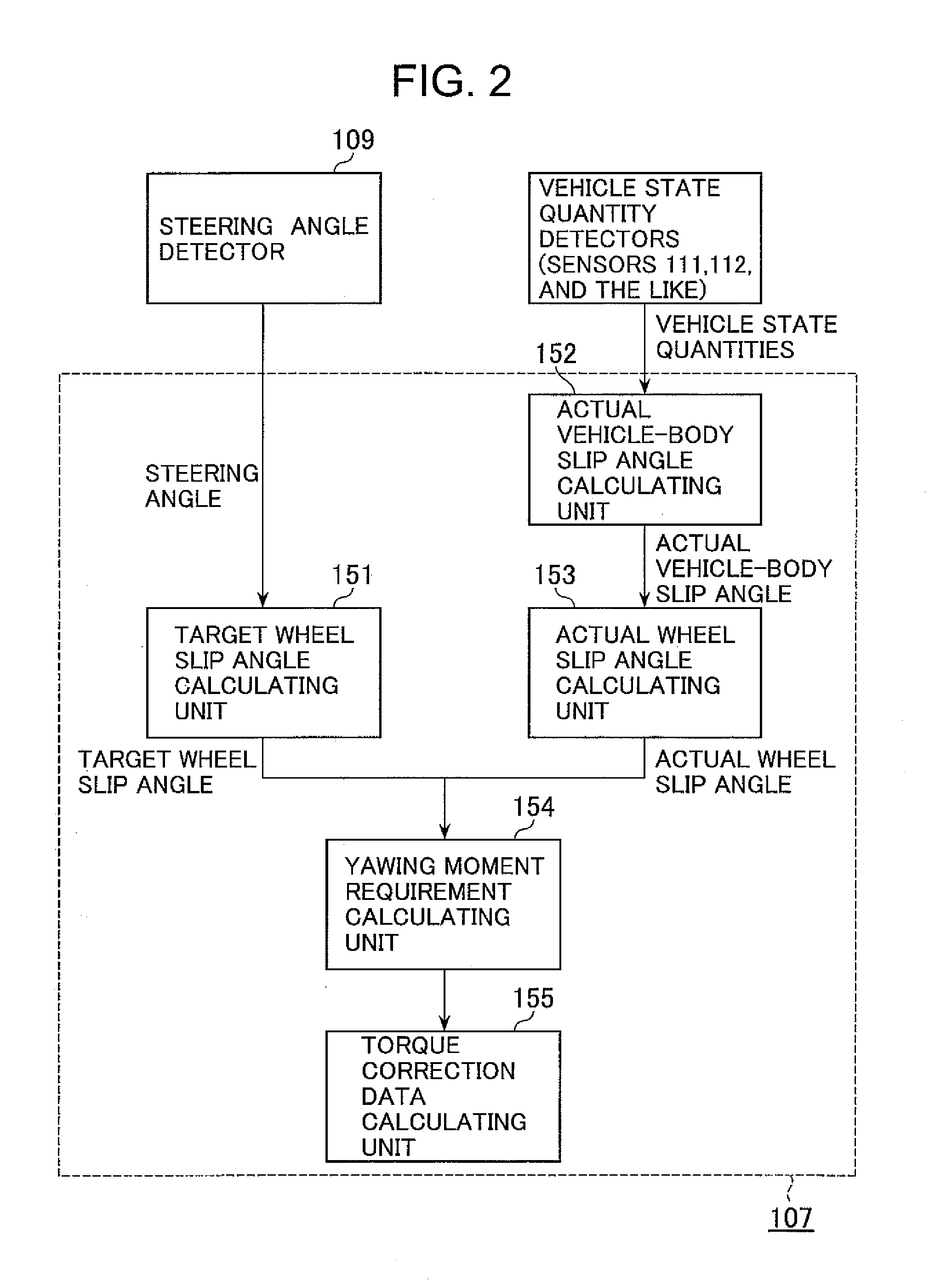
[0020]FIG. 1 is an overall block diagram of a turning motion assistance device for an electric vehicle that is the present invention.

[0021]Major constituent elements of the electric vehicle shown in FIG. 1 include one pair of steered wheels 101 and 102, a steering wheel (steering input element) 108, a turning actuator 110, an operating pedal 113, one pair of driving wheels 103 and 104, one pair of motors 105 and 106, and the turning motion assistance device 150.

[0022]The paired steered wheels 101 and 102 have a degree of rotational freedom so as to be steerable for a turn, and are each fixed to a front section of the vehicle body. The steering wheel (steering input element) 108 to which the amount of steering is input by a driver is connected to the turning actuator (steering angle controller) 110 via a steering angle sensor (steering angle detector) 109.

[0023]The turning actuator (steering angle controller) 110 that conducts steering angle control of each of the steered wheels 101 ...


PUM


Abstract

Disclosed herein is a turning motion assistance device for an electric vehicle, adapted to effectively reduce tire wear of the vehicle while at the same time ensuring appropriate turning response.A turning motion assistance device for an electric vehicle including steered wheels 101 and 102, driving wheels 103 and 104, motors 105 and 106, and a steering wheel 108 for controlling a steering angle of the steered wheels 101 and 102, includes a target wheel slip angle calculating unit 151 for calculating a target wheel slip angle from the steering angle, a vehicle state quantity detector for detecting vehicle state quantities, an actual vehicle-body slip angle calculating unit 152 for calculating an actual vehicle-body slip angle from the vehicle state quantities, an actual wheel slip angle calculating unit 153 for calculating an actual wheel slip angle from the actual vehicle-body slip angle and the steering angle, a yawing moment requirement calculating unit 154 for calculating a yawing moment requirement from a difference between the target wheel slip angle and the actual wheel slip angle, and a torque correction data calculating unit 155 for calculating an amount of torque correction for generating the yawing moment required; in this assistance device, a torque that has been corrected in accordance with the amount of torque correction is applied from the motors 105 and 106 to the driving wheels 103 and 104, respectively.

Description

BACKGROUND OF THE INVENTION[0001]1. Field of the Invention[0002]The present invention relates to a turning motion assistance device for an electric vehicle equipped with driving wheels each actuated by an independent motor.[0003]2. Description of the Related Art[0004]There are techniques available to improve the turning performance of a vehicle and stabilize its turning behavior. In such a technique, the appropriate yawing-moment target value is set according to a particular steering operation by a driver, and a driving and braking force to be imparted to left and right driving wheels is independently controlled so that a differential torque between both driving wheels is generated, thereby creating a desired yawing moment. Another technique intended to ensure turning response during the initial phase of steering and suppress uneven tire wear is described in JP-2006-282066-A, for example. In this latter technique, the camber angle of steered wheels is changed only during the initial...

Claims


Application Information

Patent Timeline
Patent Type & Authority Applications(United States)
IPC IPC(8): G06F19/00B60L15/20B60W10/00B60W10/08B60W10/18B60W10/20B60W30/00B60W30/02B60W30/045B60W30/184B60W40/06B60W40/101B60W40/103B60W40/114B62D5/04B62D6/00B62D11/04B62D113/00
CPCB60K7/0007B60L15/2036B60W40/103B60W2510/20B60W2520/14Y02T10/7275B60W2520/26B60W2720/14Y02T10/646Y02T10/648B60W2520/20Y02T10/64Y02T10/72
Inventor ICHINOSE, MASANORIYASUDA, TOMOHIKOSATO, TAKAYUKI
Owner NIHON KENKI CO LTD
Why Eureka
Try Eureka