Pneumatic Tire

a pneumatic tire and tire body technology, applied in the field of pneumatic tires, can solve the problems of reducing the edge effect, the on-ice performance accordingly, and the sipes are easily yielded adversely, and achieves the effect of large engagement force, sufficient engagement force, and large engagement for

Inactive Publication Date: 2010-08-19
TOYO TIRE & RUBBER CO LTD
View PDF7 Cites 18 Cited by
  • Summary
  • Abstract
  • Description
  • Claims
  • Application Information

AI Technical Summary

Benefits of technology

[0008]The present invention is made in view of the above-described circumstances. An object of the present invention is to provide a pneumatic tire that ensures both of the on-ice braking performance and the dry braking performance.
[0010]According to the present invention, the sipe includes a reference plane extending in the depth direction of the sipe from the wavy or zigzag line in the land portion surface. Therefore, the merit of the so-called wavy sipe can be obtained. Also, convex portions having a convex shape in the vertical section are provided to both of the front and rear sides. Therefore, irrespective of the yielding direction of the sipe, little influence is given to the yielding suppression effect. At this time, since the convex portion having a convex shape in the vertical section becomes the engagement plane, a large engagement force can be obtained in depth direction of the sipe. Further, since the engagement plane having a convex shape with respect to the reference plane is provided in a top area thereof, a large engagement force can be obtained. With this arrangement, merit of the wavy sipe and sufficient engagement force can be obtained in the depth direction of the sipe. Moreover, irrespective of the yielding direction of the sipe, little influence is given to the yielding suppression effect. Since the yielding of the sipe can be suppressed, in the pneumatic tire according to the present invention, ground-contact area of the land portion can be prevented from being reduced due to a large yielding of the sipe, and the rigidity of the entire land portion can be satisfactorily ensured.
[0011]In the pneumatic tire according to the present invention, since the ground-contact area in the land portion can be prevented from being reduced and the rigidity of the entire land portion can be satisfactorily ensured, both of the on-ice braking performance and the dry braking performance can be increased.
[0012]In the above pneumatic tire, each of the sipes is preferably further formed with a concave portion having a concave shape in the vertical section with respect to the reference plane in a top area at the front side and the rear side thereof, the concave portion preferably includes a flat plane portion located at the convex portion side as viewed in the depth direction of the sipe extending in the width direction of the sipe, and the convex portion is preferably connected to the flat plane portion. With this arrangement, when the sipe yields at brake application, due to the flat plane portion of the concave portion formed in the sipe, since the engagement force in the depth direction of the sipe is increased, the yielding of the sipe can be suppressed more effectively than the conventional manner. Additionally, since the convex portion and the flat plane portion of the concave portion are connected to each other, the yielding suppression effect of the sipe can be increased. Therefore, the ground-contact area of the land portion can be prevented from being reduced more effectively than the conventional manner as well as the rigidity of the entire land portion can be increased. As a result, both of the on-ice braking performance and the dry braking performance of the pneumatic tire can be increased with this arrangement.
[0013]In the pneumatic tire, defining the ½ length of the amplitude of the wavy or zigzag line in the surface of the land portion as T, and maximum length of the flat plane portion in the sipe width direction as T1, the lengths are preferably set to a range of 1.1T≦T1≦2T. With this arrangement, the length of the flat plane portion in the width direction of the sipe is satisfactorily ensured and the engagement force in the depth direction of the sipe is remarkably increased. Accordingly, the yielding of the sipe can be reliably suppressed. Therefore, the ground-contact area in the land portion can be reliably prevented from being reduced and the rigidity of the entire land portion can be reliably increased. As a result, with this arrangement, both of the on-ice braking performance and the dry braking performance of the pneumatic tire can be remarkably increased.
[0014]In the pneumatic tire, the concave portion is preferably connected to the end of the flat plane located at the opposite side of the convex portion and preferably has a side wall having an arc-like shape in the cross section protruding to the width direction of the sipe. With this arrangement, satisfactory length can be ensured in the sipe width direction for the flat plane portion included in the concave portion of the sipe, and a large angle can be formed between the flat plane portion and the side wall. As a result, both of the on-ice braking performance and the dry braking performance of the pneumatic tire are increased and sipe blade for forming the sipe can be manufactured easily.BRIEF DESCRIPTION OF THE DRAWINGS

Problems solved by technology

As a result, such a problem occurs.
That is, sipes are easily yielded adversely reducing the edge effect as well as the on-ice performance accordingly.
Due to the reduced rigidity of the entire land portion, such a problem also occurs.
As a result, it was found that the above-described arrangement described in Japanese Unexamined Patent Publication No. 2006-298331 fails to satisfactorily ensure the rigidity of the entire block and to suppress the yielding of sipes.
However, any of the above pneumatic tires fails to ensure sufficient rigidity of the entire block and to suppress the yielding of sipes.
Therefore, the on-ice braking performance and the dry braking performance tend to decrease.

Method used


Image

  • Pneumatic Tire
  • Pneumatic Tire
  • Pneumatic Tire

Examples


examples

[0040]Examples and Comparative Examples, which demonstrate structure and effect of the present invention, will be described below. Performance evaluation of tires was conducted as described below.

[0041](1) On-Ice Braking Performance

[0042]Test tires (size 205 / 65R15) were mounted on an actual vehicle (3000 cc class FR sedan, made in Japan), with a load of one passenger, and driven on iced road surface. While driving the vehicle at a speed of 40 km / h, brake was applied and ABS was activated. Defining braking distance of conventional tires (Comparative Example 1) as 100, the braking distance was indicated with using an index to evaluate. As the value increases, the tire exhibited more satisfactory on-ice braking performance.

[0043](2) Dry Braking Performance

[0044]Test tires (size 205 / 65R15) were mounted on an actual vehicle (3000 cc class FR sedan, made in Japan), with a load of one passenger, and driven on dry road surface (paved road). While driving the vehicle at a speed of 40 km / h, b...

example 1

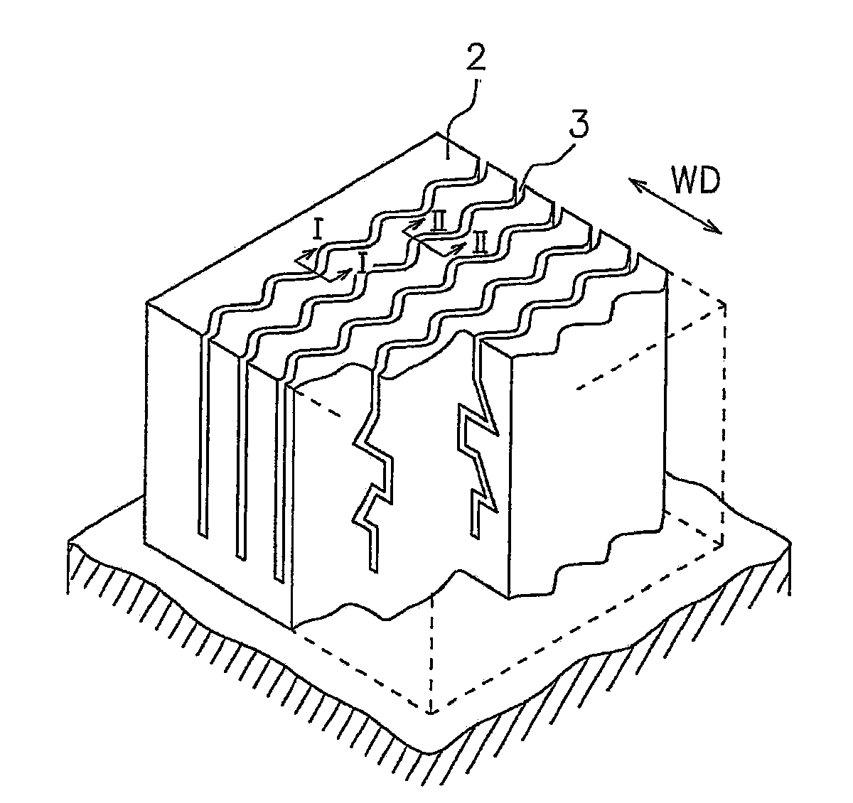
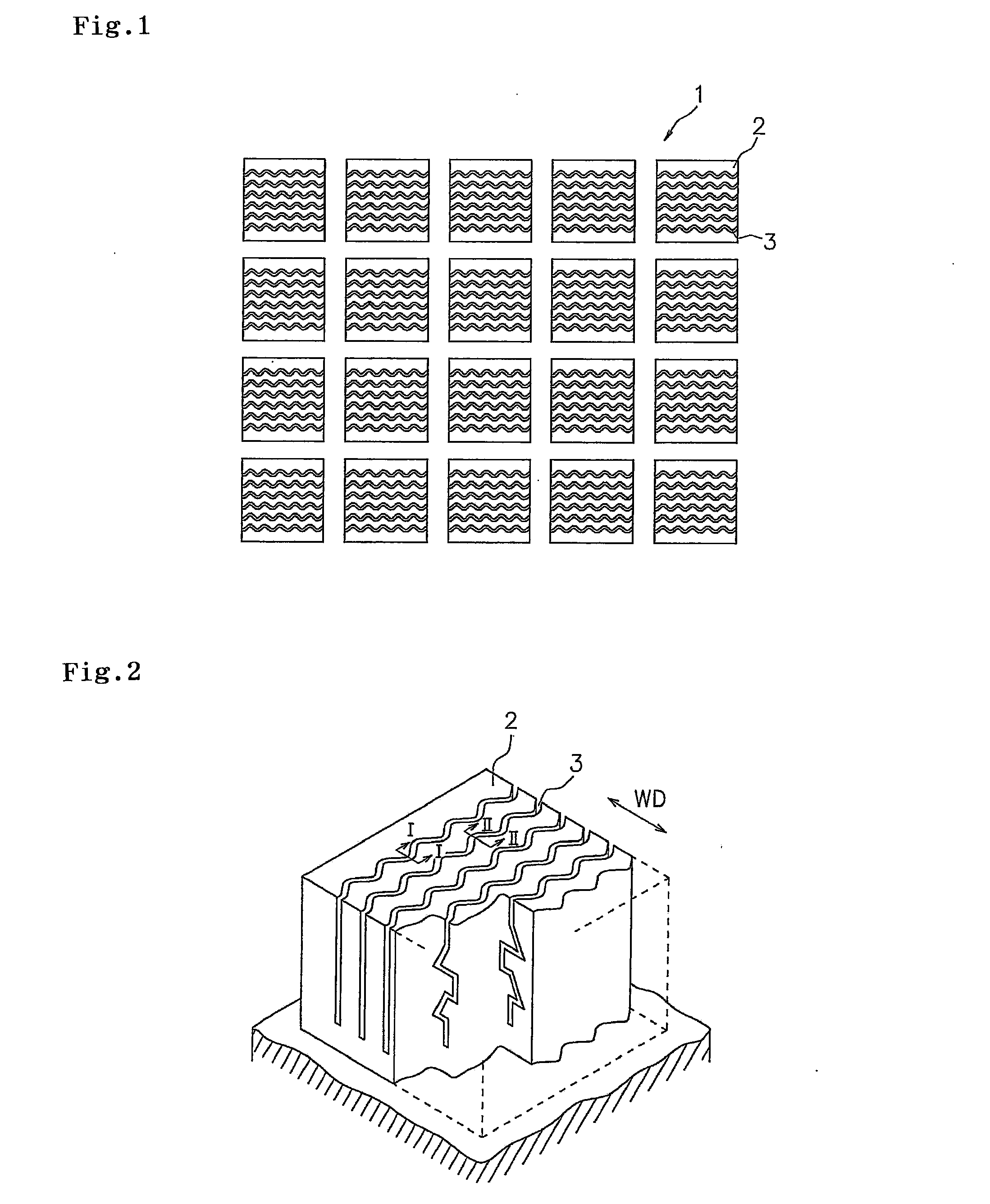
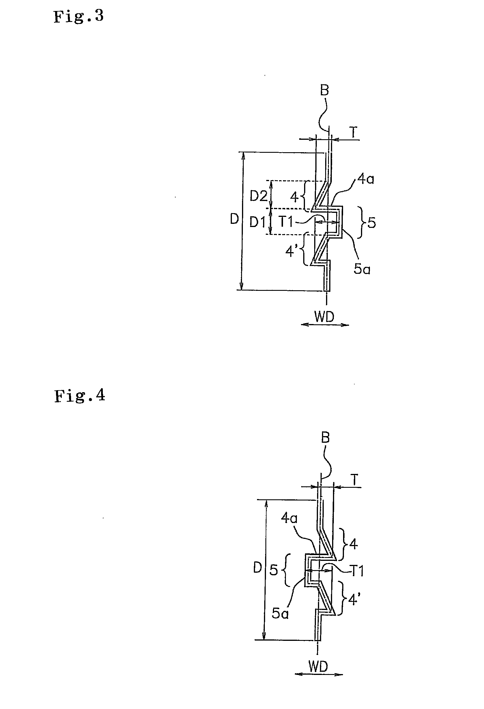
[0045]Pneumatic tires, each of which has a tread pattern shown in FIG. 1 and is formed with sipes 3 having a configuration shown in FIGS. 2 to 4, was prepared. The width of the sipe 3 was set to 0.3 mm; the depth D of the sipe 3 was set to 7 mm; ½ length T of the amplitude of the wavy line in the surface of the block 2 was set to 0.7 mm; maximum length T1 of the flat plane portion 4a of the concave portion 4 in the width direction of the sipe was set to 1.4 mm; the length D1 of the convex portion 5 in the depth direction of the sipe was set to 1.3 mm; and the length D2 of the concave portion 4 in the depth direction of the sipe was set to 1.3 mm. Using these tires, the above-described performance evaluation test was conducted. The test result is shown in Table 1.


PUM


Abstract

An object of the present invention is to provide a pneumatic tire that ensures both of the on-ice braking performance and the dry braking performance. In order to achieve the object, a pneumatic tire comprises a tread surface including a land portion in which a plurality of sipes are formed, wherein each of the sipes includes a reference plane extending in a depth direction of the sipe from a wavy or zigzag line in the surface of the land portion and each of the sipes is formed with a convex portion having a convex shape in a vertical section with respect to the reference plane in a top area at the front side and the rear side thereof.

Description

BACKGROUND OF THE INVENTION[0001]1. Field of the Invention[0002]The present invention relates to a pneumatic tire comprising a tread surface including a land portion in which a plurality of sipes is formed, particularly to a pneumatic tire useful as a winter tire.[0003]2. Description of the Related Art[0004]Conventionally, there are known winter tires in which many sipes are disposed in the respective portions (center portion, mediate portion and shoulder portion) of tire pattern in order to improve traveling performance on an iced road surface with a low friction coefficient (hereinafter, referred to as “on-ice performance”). By disposing many sipes extending in a width direction of tire in order to improve the braking performance on the iced road surface (hereinafter, referred to as “on-ice braking performance”), the edge effect in a longitudinal direction is improved. By forming such sipes in the land portion, edge effect, water removal effect and gripping effect are improved. Th...

Claims


Application Information

Patent Timeline
Patent Type & Authority Applications(United States)
IPC IPC(8): B60C11/12
CPCB60C11/12B60C2011/1213B60C11/1218
Inventor OHASHI, TOSHIYUKIMIYAZAKI, TETSUJI
Owner TOYO TIRE & RUBBER CO LTD
Why Eureka
Try Eureka