Light emitting device employing non-stoichiometric tetragonal alkaline earth silicate phosphors

a technology of alkali earth silicate and light-emitting device, which is applied in the direction of electroluminescent light sources, chemistry apparatus and processes, and leds with high power, which can solve the problems of serious disadvantage of common silicate use, increased heat loss in exciting energy form of heat, and increased heat loss of leds and especially high-power leds, so as to improve temperature and humidity stability, improve the effect of sensitivity and improved temperature stability

Active Publication Date: 2010-08-19
SEOUL SEMICONDUCTOR
View PDF27 Cites 63 Cited by
  • Summary
  • Abstract
  • Description
  • Claims
  • Application Information

AI Technical Summary

Benefits of technology

[0018]An object of the present invention is to provide a light emitting device where the decrease of brightness thereof due to the increase of temperature can be prevented or reduced.

Problems solved by technology

The LEDs and especially the High Power LEDs produce a lot of heat during operation.
Because of this, the probability of an interaction with the activator ions becomes higher, resulting in an increasing loss of exciting energy in form of heat.
This is a serious disadvantage of the use of common Silicates known until now for LED applications.
All these phosphors have the disadvantage that they have strong temperature quenching and a strong shift of the emission band with the temperature.

Method used


Image

  • Light emitting device employing non-stoichiometric tetragonal alkaline earth silicate phosphors
  • Light emitting device employing non-stoichiometric tetragonal alkaline earth silicate phosphors
  • Light emitting device employing non-stoichiometric tetragonal alkaline earth silicate phosphors

Examples


example 1

[0104]Manufacturing method of the luminescent material represented following formula 2 is described.

Cu0.05Sr2.91Si1.05O5.1:Eu0.04  [Formula 2]

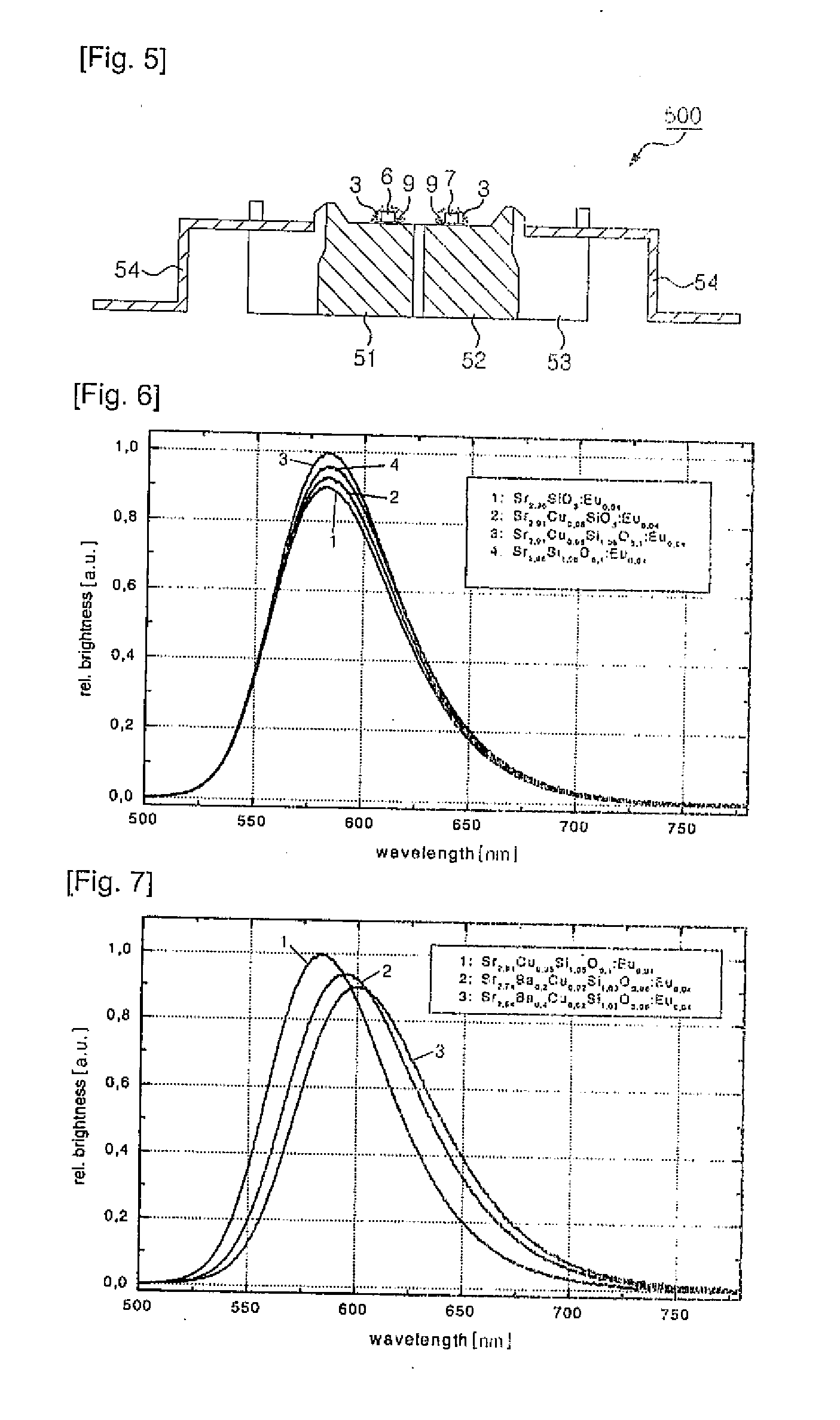
[0105]As starting materials for 1 Mol phosphor, CuO (3.98 g), SrCO3 (429.60 g), SiO2 (63.09 g), Eu2O3 (14.08 g) and / or any combinations thereof are used. The starting materials in form of very pure oxides as well as carbonates are mixed with the appropriate surplus of Silica together with small amounts of flux (NH4Cl 16 g). In a first step, the mixture is fired in an alumina crucible at 1,350° C. in an inert gas atmosphere (N2 or noble gas) for 2˜4 hours. After pre-firing, the material is milled. In a second step, the mixture is fired in an alumina crucible at 1,350° C. in weakly reducing atmosphere for additional 4 hours. Then, the material is milled, washed, dried and sieved. The luminescent material has an emission maximum at about 580 nm (shown in FIG. 7), and crystallizes in the tetragonal structure (shown in FIG. 8) which is clearly diff...

example 2

[0107]Manufacturing method of the luminescent material represented following formula 3 is described.

Cu0.02Sr2.54Ba0.4Si1.03O5.06:Eu0.04  [Formula 3]

[0108]As starting materials for 1 Mol phosphor, CuO (1.59 g), SrCO3 (375.0 g), BaCO3 (78.94 g), SiO2 (61.89 g), Eu2O3 (14.08 g) and / or any combinations thereof are used. The starting materials in form of very pure oxides as well as carbonates are mixed with a surplus of Silica together with small amounts of flux (NH4Cl −26.7 g). In a first step, the mixture is fired in an alumina crucible at 1,300° C. in an inert gas atmosphere for 2˜6 hours. After pre-firing, the material is milled again. In a second step, the mixture is fired in an alumina crucible at 1,385° C. in weakly reducing atmosphere for additional 6 hours. Then, the material is milled, washed, dried and sieved. The luminescent material has an emission maximum at about 600 nm (shown in FIG. 7). The structure is analogously to example 1 as shown in table 1 and FIG. 8.

[0109]By sub...

example 3

[0110]Manufacturing method of the luminescent material represented following formula 4 is described.

Cu0.03Sr2.92Ca0.01Si1.03O5.06:Eu0.04  [Formula 4]

[0111]As starting materials, CuO (5.57 g), SrCO3 (431.08 g), CaCO3 (1.0 g), SiO2 (61.89 g), Eu2O3 (14.08 g) and / or any combinations thereof are used. The starting materials in form of very pure oxides as well as carbonates are mixed with a surplus of Silica together with small amounts of flux (NH4Cl 24 g). In a first step, the mixture is fired in an alumina crucible at 1,300° C. in an inert gas atmosphere for 2-6 hours. After pre-firing, the material is milled again. In a second step, the mixture is fired in an alumina crucible at 1,370° C. in weakly reducing atmosphere for additional 6 hours. Then, the material is milled, washed, dried and sieved. The luminescent material has an emission maximum at 586 nm.

[0112]In the following table 2, Relative brightness of various non stoichiometric Copper Alkaline Earth Silicates at 25° C., 100° C....


PUM


Abstract

Disclosed is a light emitting device employing non-stoichiometric tetragonal Alkaline Earth Silicate phosphors. The light emitting device comprises a light emitting diode emitting light of ultraviolet or visible light, and non-stoichiometric luminescent material disposed around the light emitting diode. The luminescent material adsorbs at least a portion of the light emitted from the light emitting diode and emits light having a different wavelength from the absorbed light. The non-stoichiometric luminescent material has tetragonal crystal structure, and contains more silicon in the crystal lattice than that in the crystal lattice of silicate phosphors having stoichiometric crystal structure. The luminescent material is represented as the formula (BauSrvCawCux)3−y(Zn,Mg,Mn)zSi1+bO5+2b:Euu. Light emitting devices having improved temperature and humidity stability can be provided by employing the non-stoichiometric tetragonal Alkaline Earth Silicate phosphors.

Description

CROSS REFERENCE TO RELATED APPLICATIONS[0001]This application is the National Stage of International Application No. PCT / KR2008 / 004734, filed on Aug. 14, 2008, and claims priority from and the benefit of Korean Patent Application No. 10-2007-0086483, filed on Aug. 28, 2007, and Korean Patent Application No. 10-2008-0075181, filed on Jul. 31, 2008, which are all hereby incorporated by reference for all purposes as if fully set forth herein.BACKGROUND OF THE INVENTION[0002]1. Field of the Invention[0003]The present invention relates to a light emitting device, more particularly to a light emitting device employing non-stoichiometric tetragonal Alkaline Earth Silicate phosphors, which can be used as temperature stable luminescent material for ultraviolet or visible light excitation.[0004]2. Discussion of the Background[0005]A light emitting device (LED) has been widely used for indicators, display boards and display devices since the light emitting device can implement colors. White li...

Claims


Application Information

Patent Timeline
Patent Type & Authority Applications(United States)
IPC IPC(8): H01L33/44
CPCC09K11/7734H05B33/14H01L33/502H01L2224/48091H01L2224/48247H01L2224/8592H01L2924/19107H01L2924/181H01L2224/73265C09K11/77342H01L2924/00014H01L2924/00012
Inventor LEE, CHUNG HOONTEWS, WALTERROTH, GUNDULATEWS, STEFAN
Owner SEOUL SEMICONDUCTOR
Why Eureka
Try Eureka