Regenerative damping apparatus for vehicle

a technology of regenerative damping and vehicle, which is applied in the direction of shock absorbers, machines/engines, transportation and packaging, etc., can solve the problems of degrading the performance of the damping force of the shock absorber, generating noise, and reducing so as to maintain the driving comfort of the vehicle and/or the damping performance. , the effect of reducing the noise generated

Inactive Publication Date: 2010-08-19
HL MANDO CORP
View PDF15 Cites 36 Cited by
  • Summary
  • Abstract
  • Description
  • Claims
  • Application Information

AI Technical Summary

Benefits of technology

[0011]Accordingly, the present disclosure is conceived to solve the aforementioned problems in the prior art. An object of the present disclosure is to provide a separate regenerative damping apparatus for a vehicle in which a motion due to the vibration and / or shock generated while the vehicle is driven is converted into a rotational motion, so as to provide a regenerative damping apparatus for the vehicle in which an electric generator is allowed to regenerate the energy which would be lost, thereby capable of reducing the noise to be generated and maintaining the driving comfort of the vehicle and / or the damping performance due to its shock absorber.

Problems solved by technology

In the conventional linear-type regenerative damping apparatus, however, the ball screw device utilized for converting the reciprocating motion into the rotational motion allows the starting frictional force to be increased, so that a noise may be generated and the driving comfort may be degraded.
In addition, although the linear-type regenerative damping apparatus as described above has been mounted instead of the shock absorber, the performance in the damping force thereof is degraded compared with the shock absorber, and therefore the overall driving comfort and / or the driving performance of the vehicle has been degraded.

Method used


Image

  • Regenerative damping apparatus for vehicle
  • Regenerative damping apparatus for vehicle
  • Regenerative damping apparatus for vehicle

Examples


Embodiment Construction

[0019]Hereinafter, a preferred embodiment of the present disclosure will be described in detail with reference to the accompanying drawings.

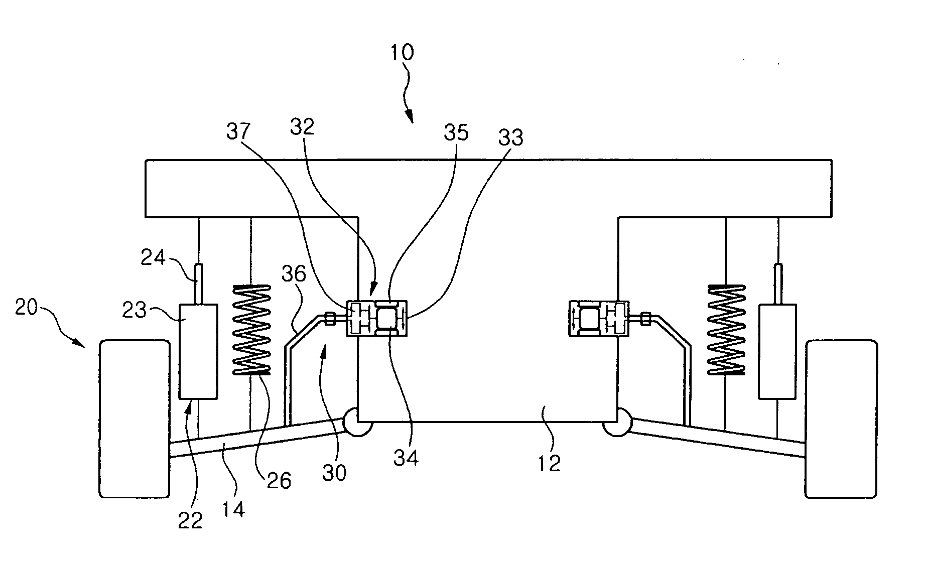
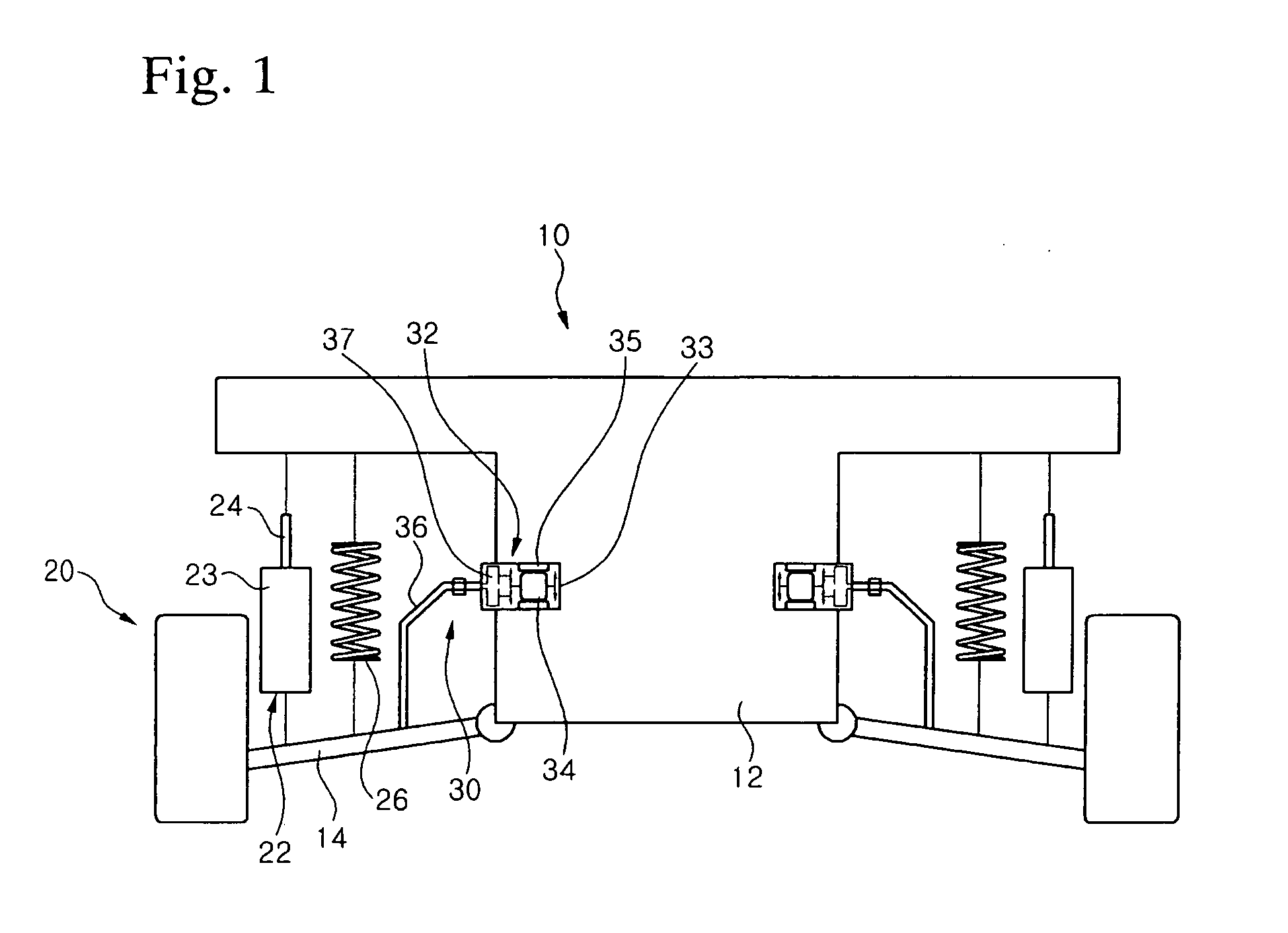
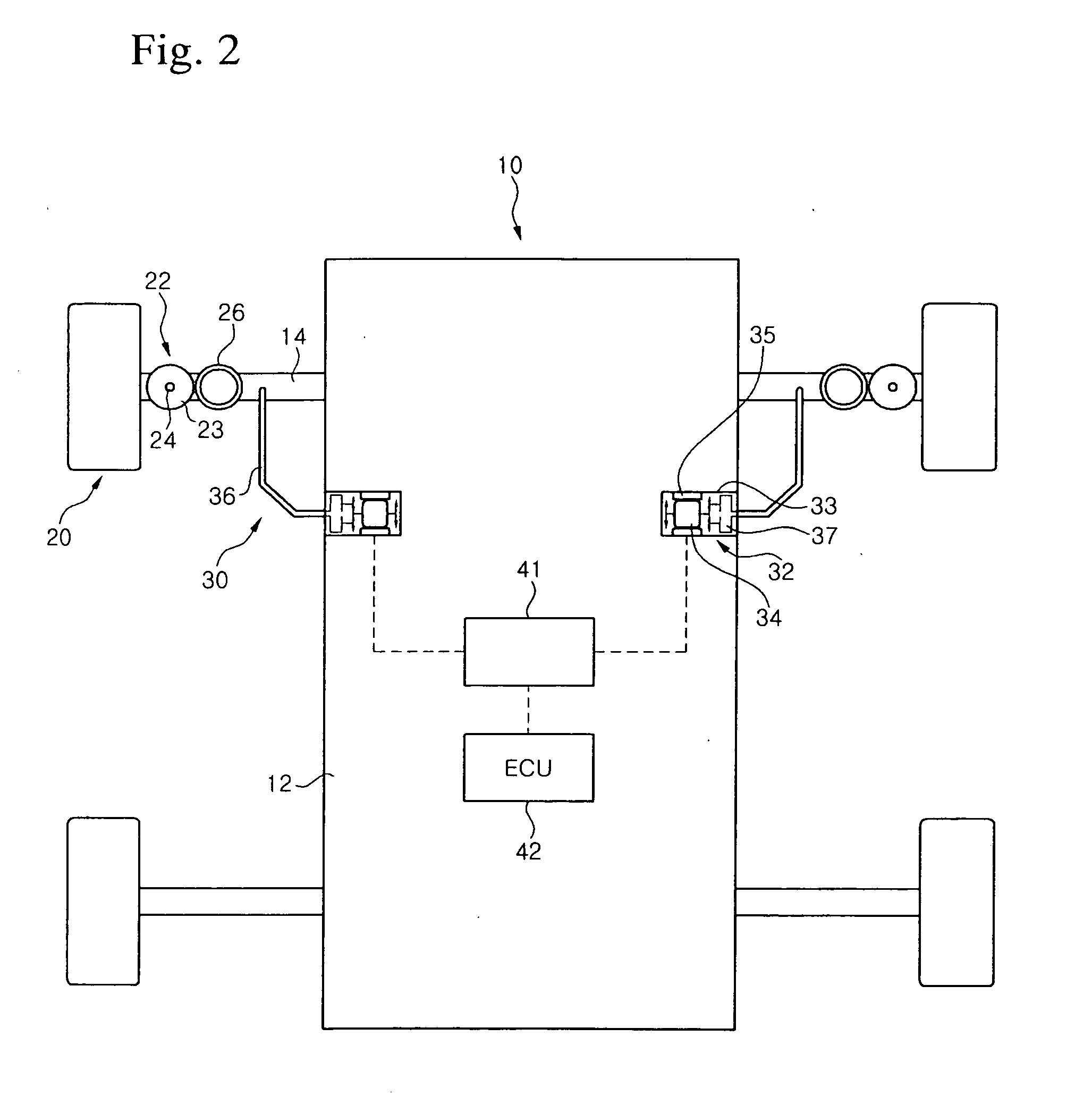
[0020]FIG. 1 is a front view illustrating a regenerative damping apparatus for a vehicle according to the present disclosure, and FIG. 2 is a plan view illustrating a regenerative damping apparatus for a vehicle according to the present disclosure.

[0021]As shown in FIGS. 1 and 2, a regenerative damping apparatus 30 according to the present disclosure is mounted to a vehicle body 10, so that it may utilize a reciprocating motion due to the vibration or the shock transmitted from a road wheel 20 to regenerate the energy which would be lost.

[0022]A shock absorber 22 comprises a cylinder 23 and a piston rod 24 mounted to be capable of being reciprocated in the cylinder 23. While the vehicle is driven, the vibration and / or the shock transmitted from the road wheel 20 allows the piston rod 24 of the shock absorber 22 to be extended / contracted from the...


PUM


Abstract

The present disclosure relates a regenerative damping apparatus for a vehicle utilizing an electric generator. An object of the present disclosure is to provide a separate regenerative damping apparatus for a vehicle in which a motion due to the vibration and / or the shock generated while the vehicle is driven is converted into a rotational motion, so as to provide a regenerative damping apparatus for the vehicle in which an electric generator is allowed to regenerate the energy which would be lost, thereby capable of reducing the noise to be generated and maintaining the driving comfort of the vehicle and / or the damping performance due to its shock absorber. In order to achieve the above object, the regenerative damping apparatus for a vehicle according to the present disclosure comprises a suspension link having one end mounted to a road wheel; and an electric generator fixed to a vehicle body with the other end of the suspension link is connected to the electric generator, thereby generating electricity by means of the rotation of the suspension link.

Description

BACKGROUND[0001]1. Technical Field[0002]The present disclosure relates to a regenerative damping apparatus for a vehicle utilizing an electric generator, and more particularly, to a regenerative damping apparatus for a vehicle, which can regenerate the energy generated in the process for damping the vibration and / or the shock transmitted from a rod surface while the vehicle is driven.[0003]2. Description of the Related Art[0004]In general, a shock absorber is mounted to a transportation means such as a vehicle and the like, so that it absorbs and damps the vibration and / or shock transmitted from a road surface to enhance driving comfort when the vehicle is driven.[0005]The shock absorber comprises a cylinder and a piston rod mounted in the cylinder in the compression and rebound manner, and the cylinder and the piston rod are mounted to a vehicle body and a road wheel or a vehicle shaft, respectively.[0006]In the shock absorber, the piston rod is reciprocated in the process for abso...

Claims


Application Information

Patent Timeline
Patent Type & Authority Applications(United States)
IPC IPC(8): F16F7/00H02K7/18
CPCB60G13/14B60G17/0157B60G2202/22B60G2202/42B60G2202/442B60G21/0555B60G2204/419B60G2300/60B60G2500/10B60G2500/20B60G2800/91B60G2204/129H02K35/00H02K41/06
Inventor PARK, KYU SHIK
Owner HL MANDO CORP
Why Eureka
Try Eureka