Multi-functional vehicle fuel display

Inactive Publication Date: 2010-08-19
FORD GLOBAL TECH LLC
View PDF10 Cites 37 Cited by
  • Summary
  • Abstract
  • Description
  • Claims
  • Application Information

AI Technical Summary

Problems solved by technology

With regard to HEVs, it is known that some drivers may not be able to achieve desired fuel economy numbers, in part because of driving habits.
In many cases, drivers are willing to modify their behavior, but are unable to translate recommended techniques into real changes in

Method used


Image

  • Multi-functional vehicle fuel display
  • Multi-functional vehicle fuel display
  • Multi-functional vehicle fuel display

Examples


Example

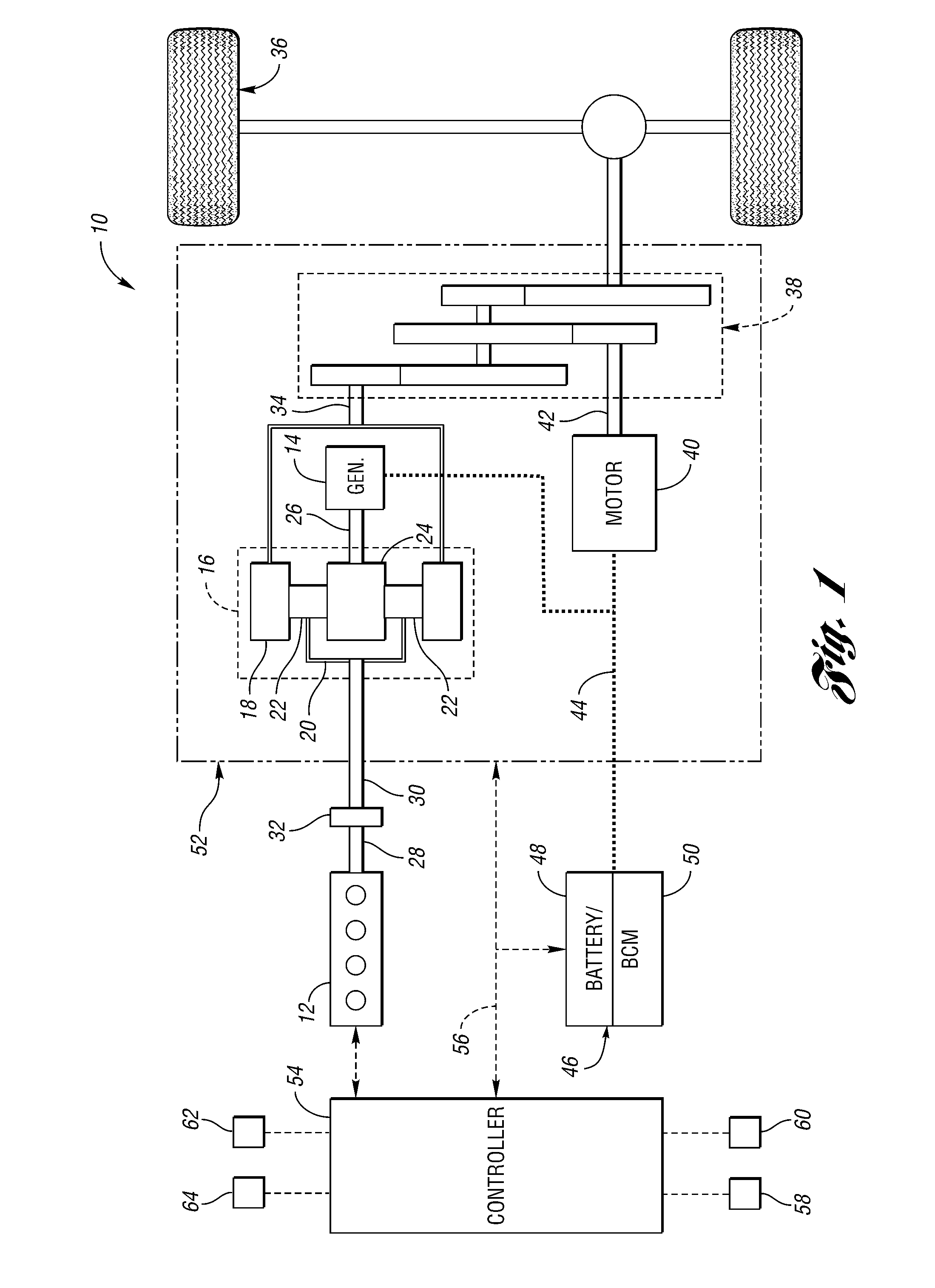
[0014]FIG. 1 shows a schematic representation of a vehicle 10, which includes an engine 12 and an electric machine, or a generator 14. The engine 12 and the generator 14 are connected through a power transfer arrangement, which in this embodiment, is a planetary gear arrangement 16. Of course, other types of power transfer arrangements, including other gear sets and transmissions, may be used to connect the engine 12 to the generator 14. The planetary gear arrangement 16 includes a ring gear 18, a carrier 20, planet gears 22, and a sun gear 24.

[0015]The generator 14 can also output torque to a shaft 26 connected to the sun gear 24. Similarly, the engine 12 outputs torque to a crankshaft 28, which is connected to a shaft 30 through a passive clutch 32. The clutch 32 provides protection against over-torque conditions. The shaft 30 is connected to the carrier 20 of the planetary gear arrangement 16, and the ring gear 18 is connected to a shaft 34, which is connected to a first set of v...


PUM


Abstract

A multi-functional, composite fuel display for displaying both fuel level information and fuel economy information is provided. The fuel level is displayed using a plurality of bar segments, each corresponding to a single unit of fuel. Once a single unit of fuel is consumed, the corresponding bar segment changes size to indicate an average fuel economy for that unit of fuel. The bar segment corresponding to the current unit of fuel being consumed changes size in real time to indicate instantaneous fuel economy. An indicator is provided over the bar segments corresponding to single unit of consumed fuel to indicate average fuel economy for the current tank of fuel.

Description

BACKGROUND[0001]1. Technical Field[0002]One or more embodiments of the present application relate to a system and method for displaying instantaneous fuel economy, average fuel economy, and fuel tank level using an information display within a vehicle.[0003]2. Background Art[0004]Vehicles, whether passenger or commercial, include a number of gauges, indicators, and various other displays to provide the vehicle operator with information regarding the vehicle and its surroundings. With the advent of new technologies, such as hybrid electric vehicles (HEVs), has come a variety of new gauges and information displays that help operators to better learn the operation of these vehicles that utilize new technology. For example, many HEVs incorporate gauges that attempt to provide the operator with information on the various hybrid driving states. These gauges indicate to the operator when the vehicle is being propelled by the engine alone, the motor alone, or a combination of the two. Simil...

Claims


Application Information

Patent Timeline
IPC IPC(8): B60Q1/00
CPCB60K35/00B60Y2200/90B60K2350/1092B60K2350/1064B60K2370/154B60K2370/174Y02T10/84
Inventor WATSON, ANGELA L.BISHOP, STEVENMERCHANT, SOHELSANDVIG, CRAIGHERNANDEZ, IVETTEWATSON, DAVIDERDOGAN, ENGINSENDIL, ALTAY JUN WAKUISTAGE, SUSANNE
Owner FORD GLOBAL TECH LLC
Why Eureka
Try Eureka