

Optical Sensing Screen and Panel Sensing Method
a sensing screen and optical technology, applied in the field of optical sensing screens and panel sensing methods, can solve the problems of inability to operate with fingers, inability to detect signals, and inability to correct the detection effect of signals
- Summary
- Abstract
- Description
- Claims
- Application Information
AI Technical Summary
Benefits of technology
Problems solved by technology
Method used
Image

Examples
first embodiment
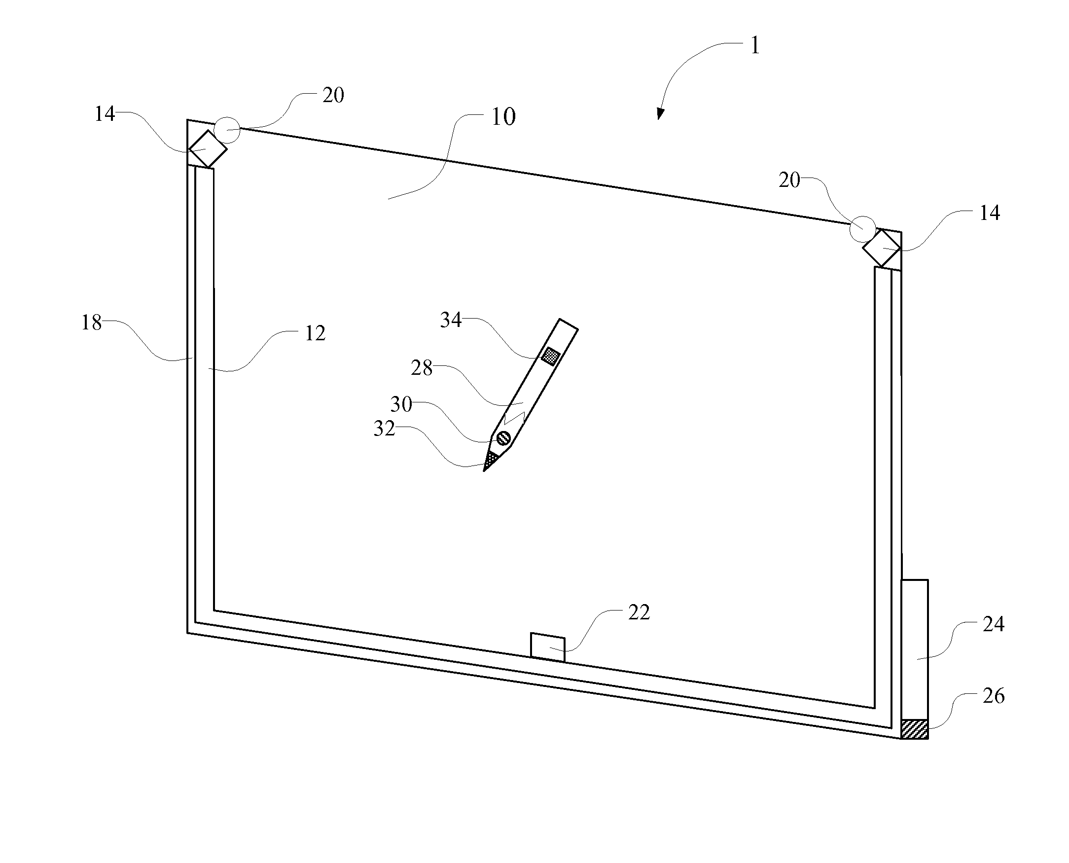
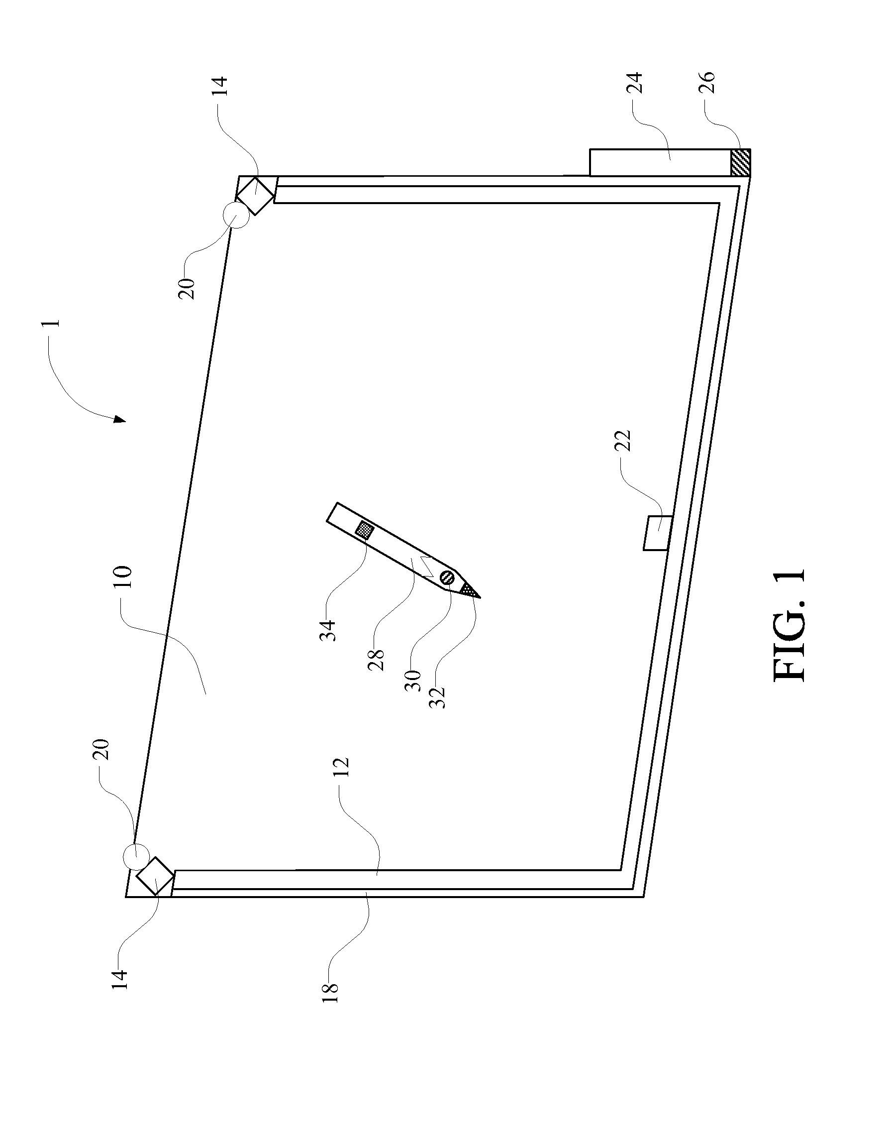
[0037]Please refer to FIG. 2. FIG. 2 is a schematic diagram illustrating the optical sensing screen 1 of the invention. The sensing field of the first photo-sensing device 14 includes a three-dimensional space, and the space can be detected by the first photo-sensing 14 is defined as a writing space, such as the space covered by the dash line in FIG. 2. In the embodiment, the optical sensing screen 1 of the invention includes more than two first photo-sensing devices 14, and all of the sensing spaces of the first photo-sensing devices 14 can be combined and defined to be a writing space. The optical sensing screen 1 is switched between the passive touch mode and active touch mode by detecting whether the light pen 28 is in the writing space. If light pen 28 exists, the optical sensing screen 1 switches to the active touch mode. If light pen 28 does not exist, the optical sensing screen 1 switches to the passive touch mode.
second embodiment
[0038]Please refer to FIG. 3. FIG. 3 is a schematic diagram illustrating the optical sensing screen 1 of the invention. In the embodiment, the optical sensing screen 1 of the invention uses more than one additional second photo-sensing device 22 to form a writing space, and the function of the second photo-sensing devices 22 is different from that of the first photo-sensing device 14 which is used to position. All the sensing fields of the second photo-sensing devices 22 can be combined and defined to be a writing space, such as the space covered by the dash line in FIG. 3. The optical sensing screen 1 is switched between the passive touch mode and active touch mode by detecting whether the light pen 28 is in the writing space. If light pen 28 exists, the optical sensing screen 1 switches to the active touch mode. If light pen 28 does not exist, the optical sensing screen 1 switches to the passive touch mode.
third embodiment
[0039]Please refer to FIG. 4. FIG. 4 is a schematic diagram illustrating the optical sensing screen 1 of the invention. In the embodiment, a pen holder 24 for placing the light pen 28 is disposed to the optical sensing screen 1 of the invention. The pen holder 24 includes a sensor 26. When the light pen 28 is pulled out from the pen holder 24, the optical sensing screen 1 is switched from the passive touch mode to the active touch mode and the user can use the light pen 28 to write. When light pen 28 is received in the pen holder 24, the optical sensing screen 1 is switched to the passive touch mode and inputting by using an object to touch is allowed. The connection between the light pen 28 and processor can be wired or wireless. The light pen 28 actively transmits control signals to the processor and controls the optical sensing screen 1 of the invention to be switched between the passive touch mode and the active touch mode.
[0040]Compared with prior arts, the optical sensing scre...
PUM
 Abstract
Description
Claims
Application Information