
Controlling sheet registration in a digital printing system

a digital printing system and sheet registration technology, applied in the field of digital printing systems, can solve problems such as troublesome, sheet misregistration on the second photoreceptor, and encountered problems

Active Publication Date: 2010-08-19
XEROX CORP
View PDF4 Cites 6 Cited by
  • Summary
  • Abstract
  • Description
  • Claims
  • Application Information

AI Technical Summary

Benefits of technology

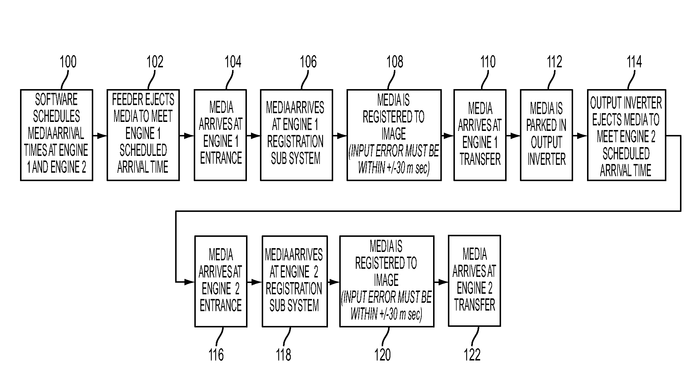
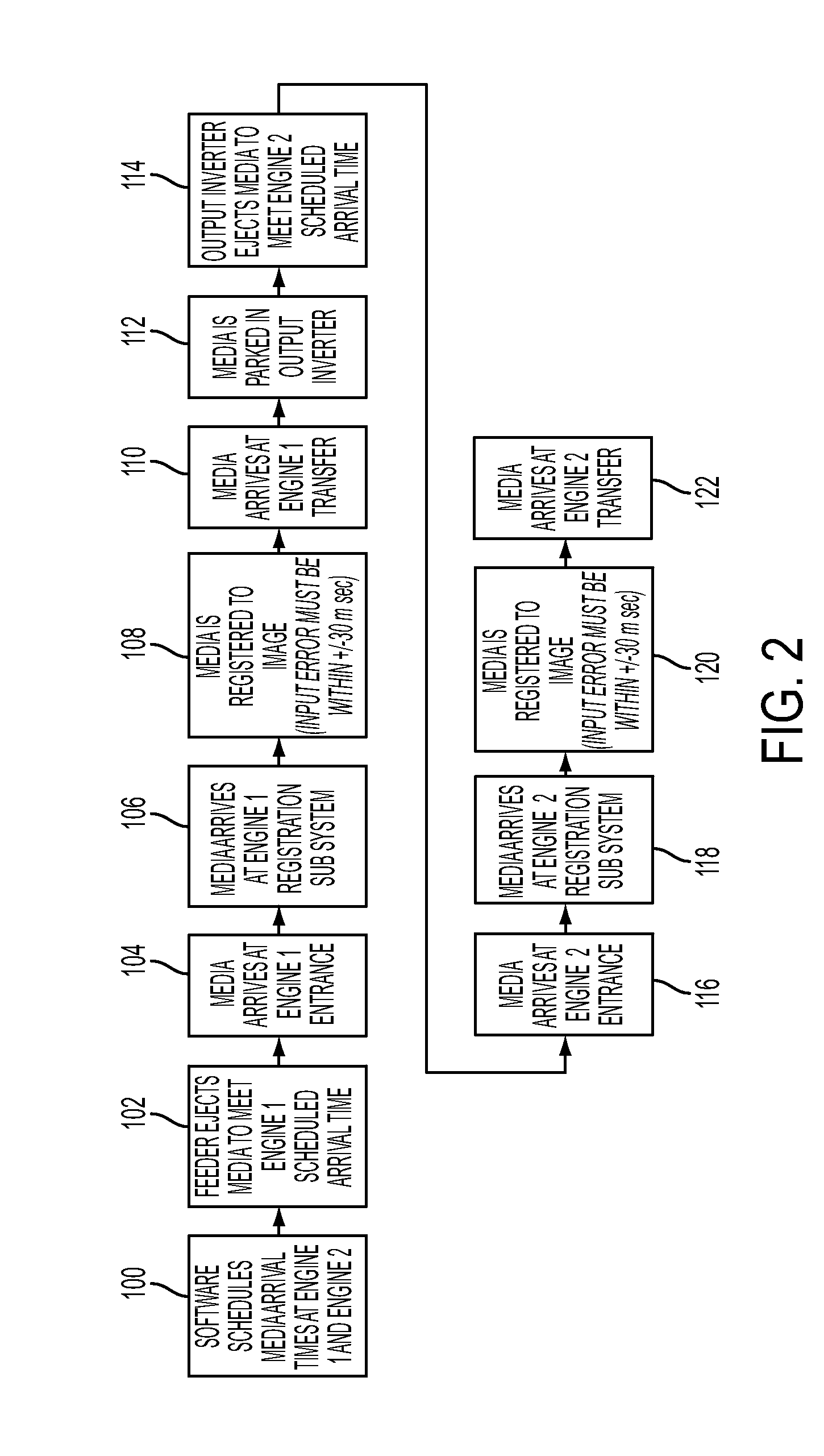
[0005]The present disclosure describes a digital printing system employing tandem marking engines for duplex printing and utilizes a variable dwell time in the output inverter of the first marking engine to provide for correct positioning of the leading edge of the inverted sheet for arrival at the entrance of the second marking engine. The system presently disclosed avoids the seam in the photoreceptor of the second marking engine and properly positions the leading edge of the sheet for correct front-to-back image registration on the second photoreceptor for image transfer to the sheet. The system of the present disclosure thus eliminates the need to synchronize the seam positions of the photoreceptors in the tandem marking engines and permits the speed of the photoreceptor in the second marking engine to be varied for purposes of controlling the image magnification thereon without regard to seam position.

Problems solved by technology

However, in printing systems of this type arrangement, problems have been encountered in proper registration of the leading edge of the inverted sheet onto the photoreceptor of the second printing engine for proper placement of the image on the sheet and for avoiding the seam in the photoreceptor of the second marking engine.
Where the inverted sheet from the first marking engine is transported by a transporter to the second marking engine, errors in timing, transport speed and positioning of the sheet can accumulate to cause misregistration of the sheet on the second photoreceptor.
This is particularly troublesome in view of the requirement that the sheet be placed on the second photoreceptor within a window of plus or minus 30 milliseconds timing with respect to the movement of the photoreceptor.
Typically, tandem marking engines employed for duplex printing operate to synchronize the position of the seams by varying the speed of the photoreceptor in the second marking engine and can result in problems with front to back image-to-paper registration due to paper shrinkage from heating in the first marking engine's fuser and differences in the photoreceptor belt length causing varied photoreceptor speed.

Method used


Image

  • Controlling sheet registration in a digital printing system
  • Controlling sheet registration in a digital printing system
  • Controlling sheet registration in a digital printing system

Examples


Embodiment Construction

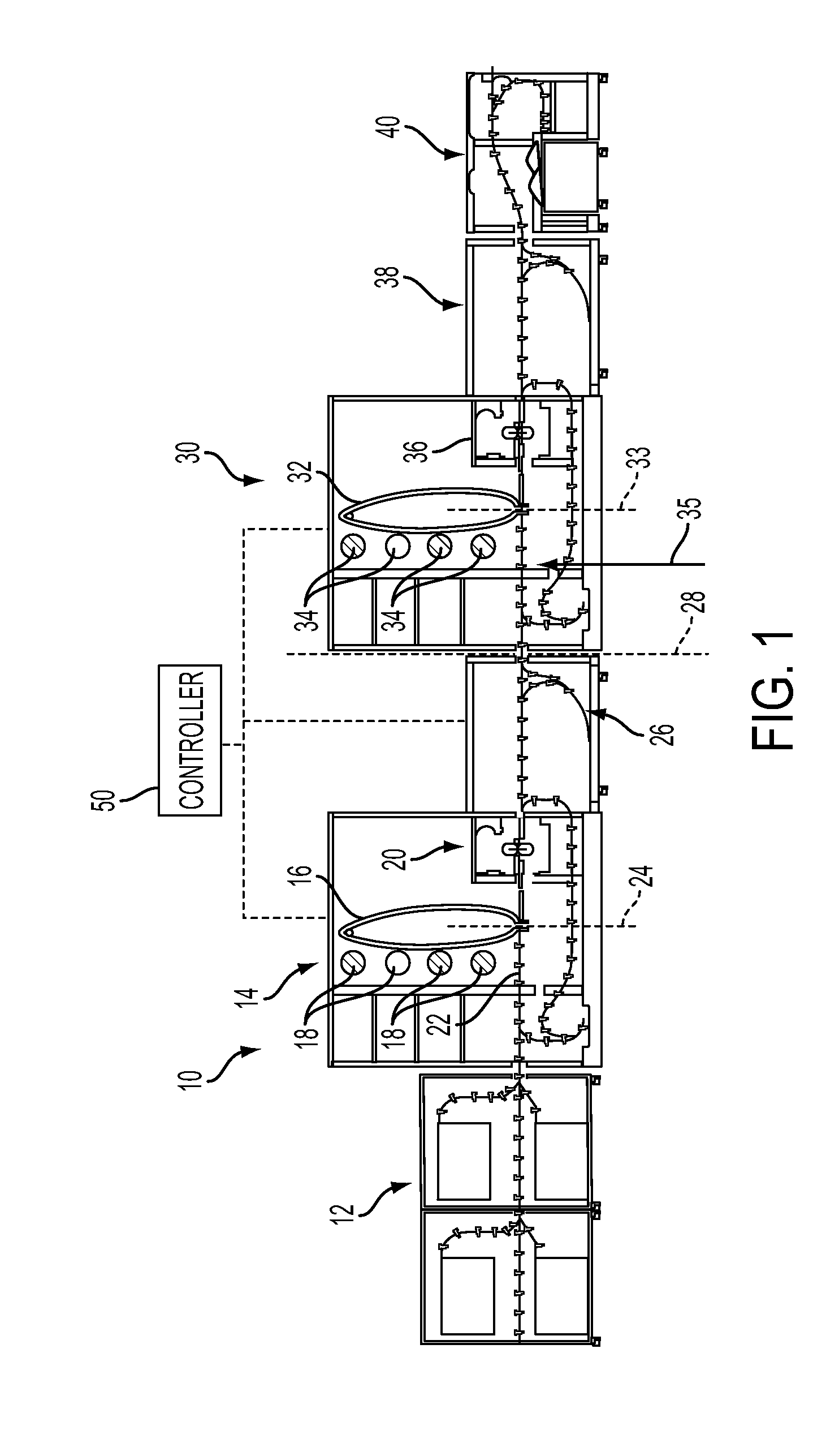
[0009]Referring to FIG. 1, a digital printing system according to the present disclosure is indicated generally at 10 and includes a sheet feeder assembly indicated generally at 12, a first marking engine indicated generally at 14 including a photoreceptor belt 16 of the endless seamed type and a plurality of colorant generators 18 operative for effecting color image formation on the belt 16. The marking engine 14 includes a fuser indicated generally at 20 and a transporter providing a transport path 22 through the marking engine. The photoreceptor 16 is operative to transfer the image to the sheet stock on path 22 at a transfer station indicated in dashed outline and denoted with reference numeral 24.

[0010]From the marking at station 24, the sheet stock is advanced along path 22 and is discharged from the fuser 20 along path 22 to an inverter 26 which inverts the marked sheet and maintains the sheet for a controlled dwell time before reentry onto the path 22 and movement to the ent...


PUM


Abstract

A digital printing system employing tandem marking engines for duplex printing utilizing a variable dwell time in the output sheet inverter of the first marking engine to provide correct positioning of the leading edge of the inverted sheet for arrival at the entrance of the second marking to avoid the seam in the photoreceptor.

Description

BACKGROUND[0001]The present disclosure relates to digital printing systems having plural tandem marking or printing engines of the type with seamed endless photoreceptor belts. In such printing systems, it is common practice to invert the sheet after marking on one side thereof in a first of the printing engines and for feeding the inverted sheet into a second printing engine for marking on the opposite side of the sheet to thus facilitate high speed duplex digital printing. However, in printing systems of this type arrangement, problems have been encountered in proper registration of the leading edge of the inverted sheet onto the photoreceptor of the second printing engine for proper placement of the image on the sheet and for avoiding the seam in the photoreceptor of the second marking engine. Where the inverted sheet from the first marking engine is transported by a transporter to the second marking engine, errors in timing, transport speed and positioning of the sheet can accum...

Claims


Application Information

Patent Timeline
Patent Type & Authority Applications(United States)
IPC IPC(8): G03G15/00
CPCG03G15/65G03G2215/00599G03G2215/00021
Inventor TOOKER, ANA P.DIEHL, MICHAEL JAMESENZIEN, COLLEEN R.HIGGINS, THOMAS EDWARDKRETSCHMANN, DAVID ROBERTLOPEZ, CARLOS A.BONACCI, ANDREW JAMESTYSON, JACQUELINE YVONNE
Owner XEROX CORP
Learn More