Grain cart with folding auger

a cart and auger technology, applied in the field of grain carts, can solve the problems of reducing the efficiency of the auger, so as to enhance the forward and/or lateral reach enhance the operating offset angle, and enhance the effect of the auger assembly

Inactive Publication Date: 2010-08-19
UNVERFERTH MFG
View PDF4 Cites 25 Cited by
  • Summary
  • Abstract
  • Description
  • Claims
  • Application Information

AI Technical Summary

Benefits of technology

[0008]One aspect of the present invention provides a grain cart comprising a wheeled frame; a container mounted on the frame and configured to hold a quantity of grain, the container having front, rear and laterally opposed side walls; a folding auger assembly having upper and lower auger assembly portions connected by a joint assembly, the lower auger assembly portion having a lower auger housing with first and second ends and a lower auger portion rotatably disposed in the lower auger housing, and the upper auger assembly portion having an upper auger housing with first and second ends and an upper auger portion rotatably disposed in the upper auger housing; wherein the first end of the lower auger housing has an intake opening proximate a bottom of the container to receive grain and the second end of the lower auger housing is disposed adjacent a forward corner of the container where the front wall intersects one of the laterally opposed side walls; wherein the first end of the upper auger housing is disposed adjacent the second end of the lower auger housing and the second end of the upper auger housing has a discharge opening to discharge grain from the container; and wherein the joint assembly defines a pivot axis about which the upper auger assembly portion is pivotable relative to the lower auger assembly portion between an operating position in which the first end of the upper auger assembly portion abuts the second end of the lower auger assembly portion to permit grain to be discharged from the container and a transport position in which the upper auger assembly portion extends downwardly from the second end of the lower auger assembly portion diagonally across the front wall of the container substantially between the laterally opposed side walls of the container to facilitate transporting the grain cart. When in the operating position, the upper auger assembly portion can be offset from the lower auger assembly portion by an operating offset angle. When in a transport position, the upper auger assembly portion can be offset from the lower auger assembly portion by a transport offset angle. In an embodiment, the pivot axis is oblique to at least one, and preferably both, of the respective longitudinal axes of the upper and lower auger assembly portions to improve reach in the operating position and / or reduce size in the transport position.
[0021]An advantage of folding the upper auger assembly portion diagonally across the front of the cart as described herein is that the auger assembly can be made longer to provide enhanced reach in the operating position. Orienting the upper auger assembly at an operating offset angle relative to the lower auger assembly in the operating position can further enhance forward and / or lateral reach of the auger assembly. Use of a universal joint to couple the upper and lower auger portions is also advantageous because it allows a larger operating offset angle and thus improved reach. Having the upper auger assembly pivot about an obliquely oriented pivot axis is further advantageous in that the upper auger assembly can be made to pivot in closer proximity to the cart thereby facilitating front folding without hitting the tractor.

Problems solved by technology

As a grain cart with a fully extended auger can be somewhat unwieldy during transport, many grain carts employ folding augers that can open to an operating position and fold to a transport position.
For instance, none of them maximize side and forward reach when in an operating position and minimize transport size when in a transport position.
Another disadvantage of prior art folding augers is that the folding motion may not clear the cab of some tractors, making it difficult to convert the auger between operating and transport positions.

Method used


Image

  • Grain cart with folding auger
  • Grain cart with folding auger
  • Grain cart with folding auger

Examples


Embodiment Construction

[0032]While the present invention may be embodied in many different forms, a number of illustrative embodiments are described herein with the understanding that the present disclosure is to be considered as providing examples of the principles of the invention and such examples are not intended to limit the invention to preferred embodiments described herein and / or illustrated herein.

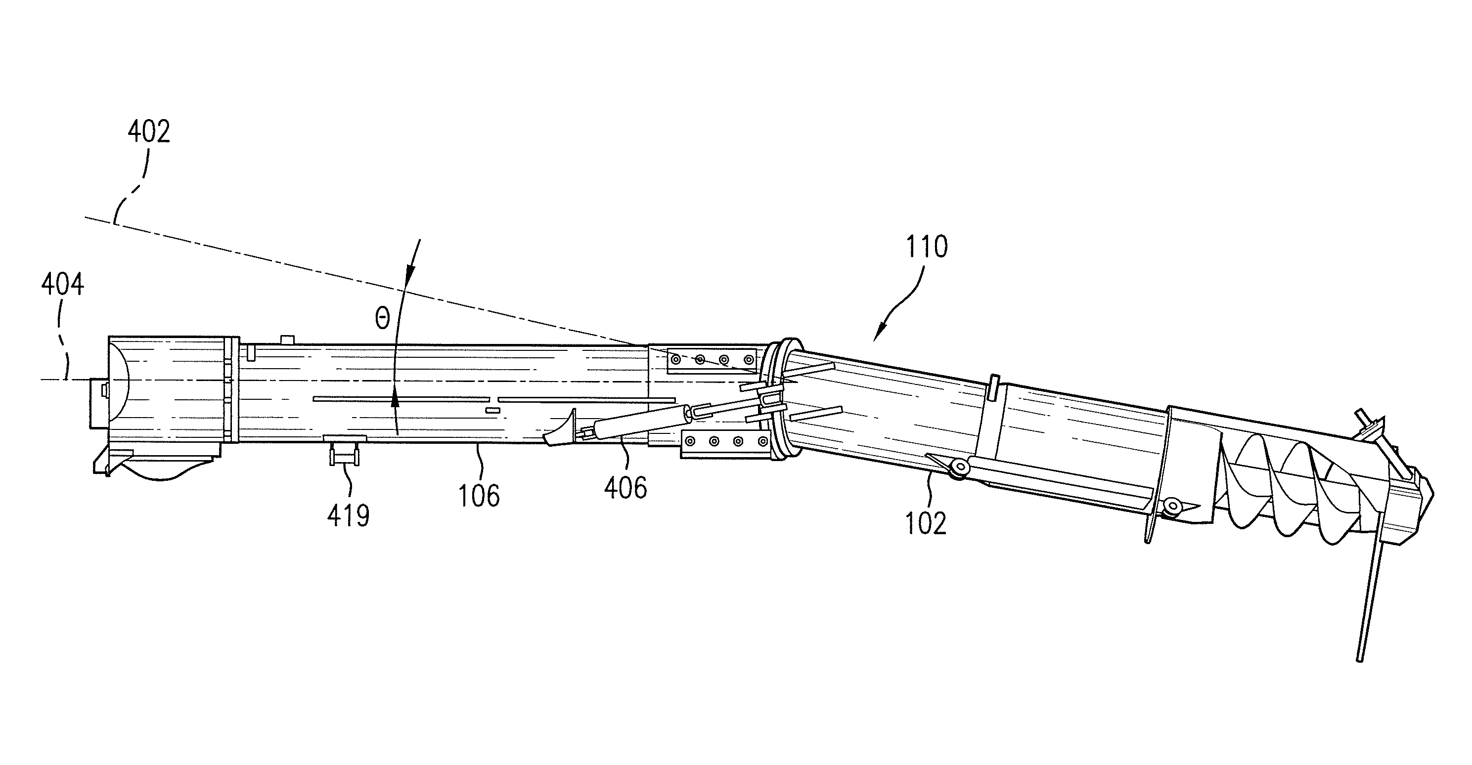
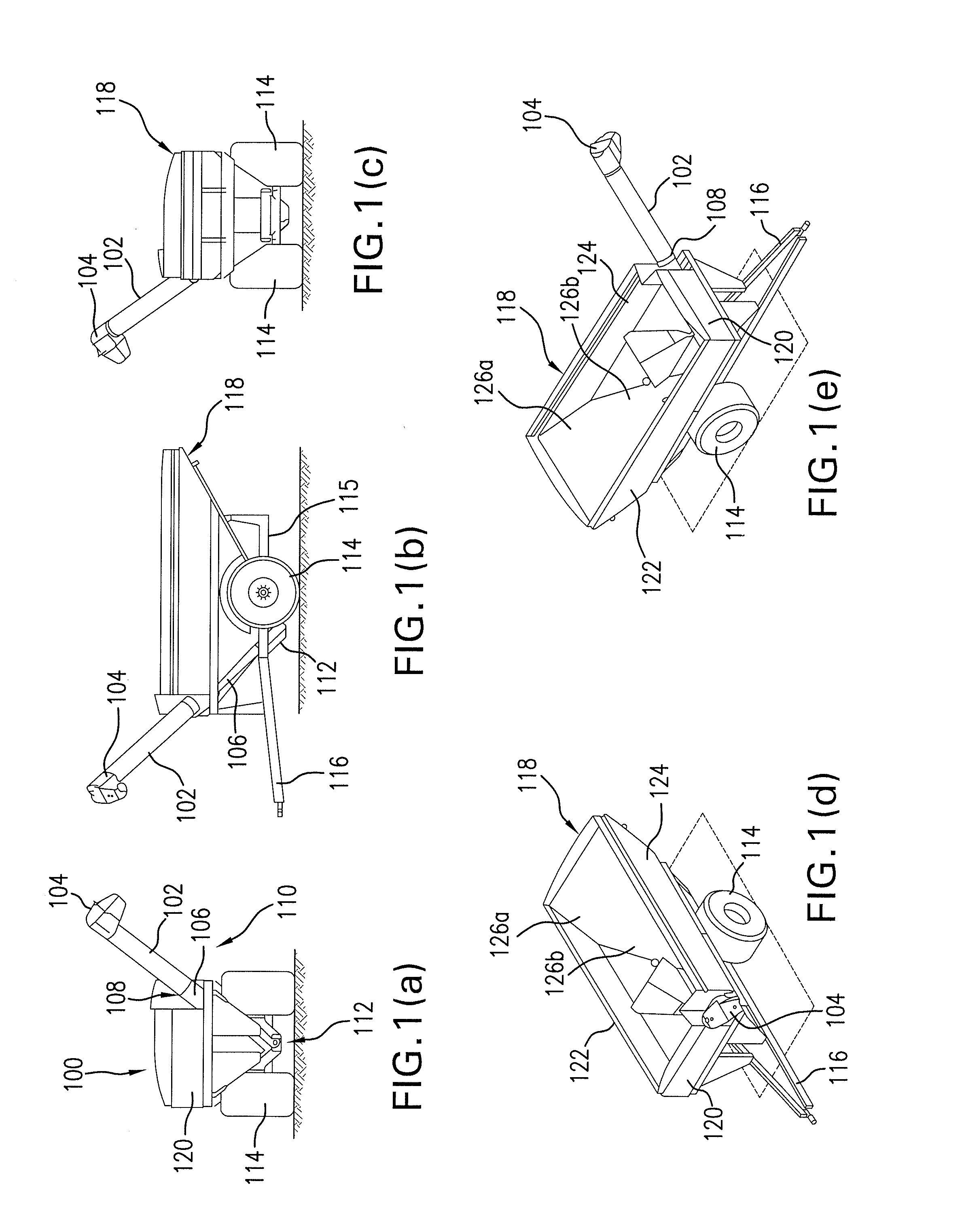
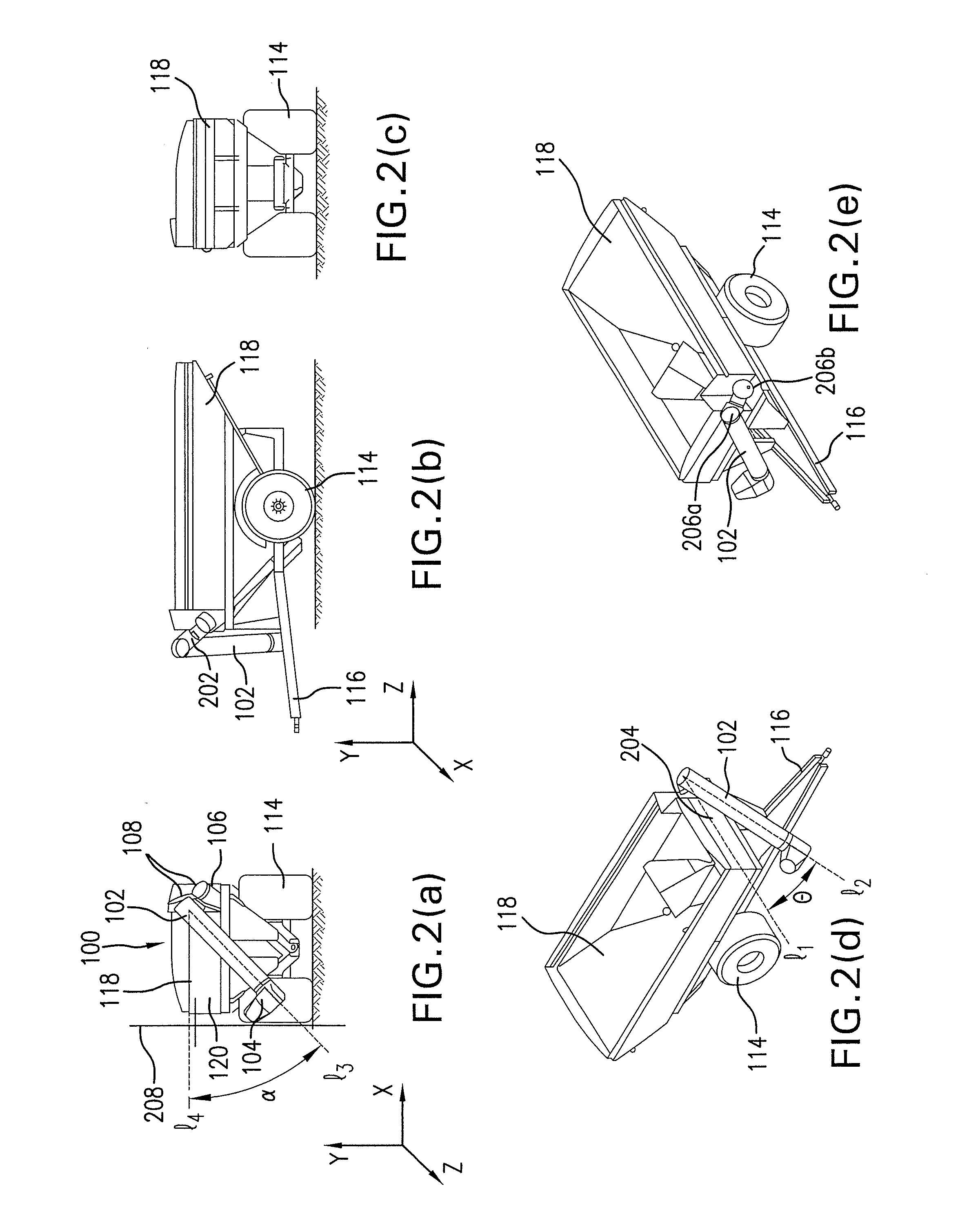
[0033]FIGS. 1(a)-(e) depict a grain cart 100 with a front-folding auger assembly 110 in an operating position according to an embodiment of the present invention. The grain cart includes a grain holding container or hopper 118 mounted on a frame 115 with wheels 114 and a hitch 116. The hopper 118 has a front wall or side 120, laterally opposed side walls 122 and 124, and a rear wall or side composed of upper and lower rear wall portions 126a and 126b, which together define a grain holding space with an open top and a bottom. As best seen in FIGS. 1(d) & (e), the upper rear wall portion 126a extends down...


PUM


Abstract

A grain cart and foldable auger assembly having an upper auger assembly portion with a discharge portion, a lower auger assembly portion with an intake portion, and a compound angle joint that allows the upper auger assembly portion to be moved between operating and transport positions. When in an operating position, the upper auger portion and the lower auger portion are offset from each other by an operating offset angle. When in a transport position, the upper auger assembly portion is offset from the lower auger assembly portion by a transport offset angle such that the upper auger assembly portions folded across the front of the grain cart in a non-obstructive and non-protruding manner.

Description

CROSS-REFERENCE TO RELATED APPLICATIONS[0001]This application claims the benefit of U.S. Provisional Patent Application Ser. No. 61 / 152,521, filed on Feb. 13, 2009, and U.S. Provisional Patent Application Ser. No. 61 / 228,284, filed on Jul. 24, 2009, the disclosures of which are incorporated herein in their entirety.BACKGROUND OF THE INVENTION[0002]1. Field of the Invention[0003]The present invention relates generally to grain carts and, more particularly, to grain carts having folding augers.[0004]2. Description of the Related Art[0005]In agriculture, augers are frequently used to move material from a cart to another cart, silo, truck, or other storage facility. Augers used to move grain are known as grain augers and are frequently employed in grain carts. A typical grain auger includes an auger screw of constant diameter and pitch that is housed inside a tubular housing or shaft to form an auger assembly. An intake portion of the auger assembly can draw from a hopper (usually by gr...

Claims


Application Information

Patent Timeline
Patent Type & Authority Applications(United States)
IPC IPC(8): B60P1/42
CPCB60P1/42A01F12/46A01D90/10A01B73/00B65G67/24
Inventor VAN MILL, MICHAEL D.SCHLIMGEN, RONALD J.WALVATNE, JOHNSELF, CHRISTOPHER M.
Owner UNVERFERTH MFG
Why Eureka
Try Eureka