

Object location and movement detection system and method
- Summary
- Abstract
- Description
- Claims
- Application Information
AI Technical Summary
Benefits of technology
Problems solved by technology
Method used
Image

Examples
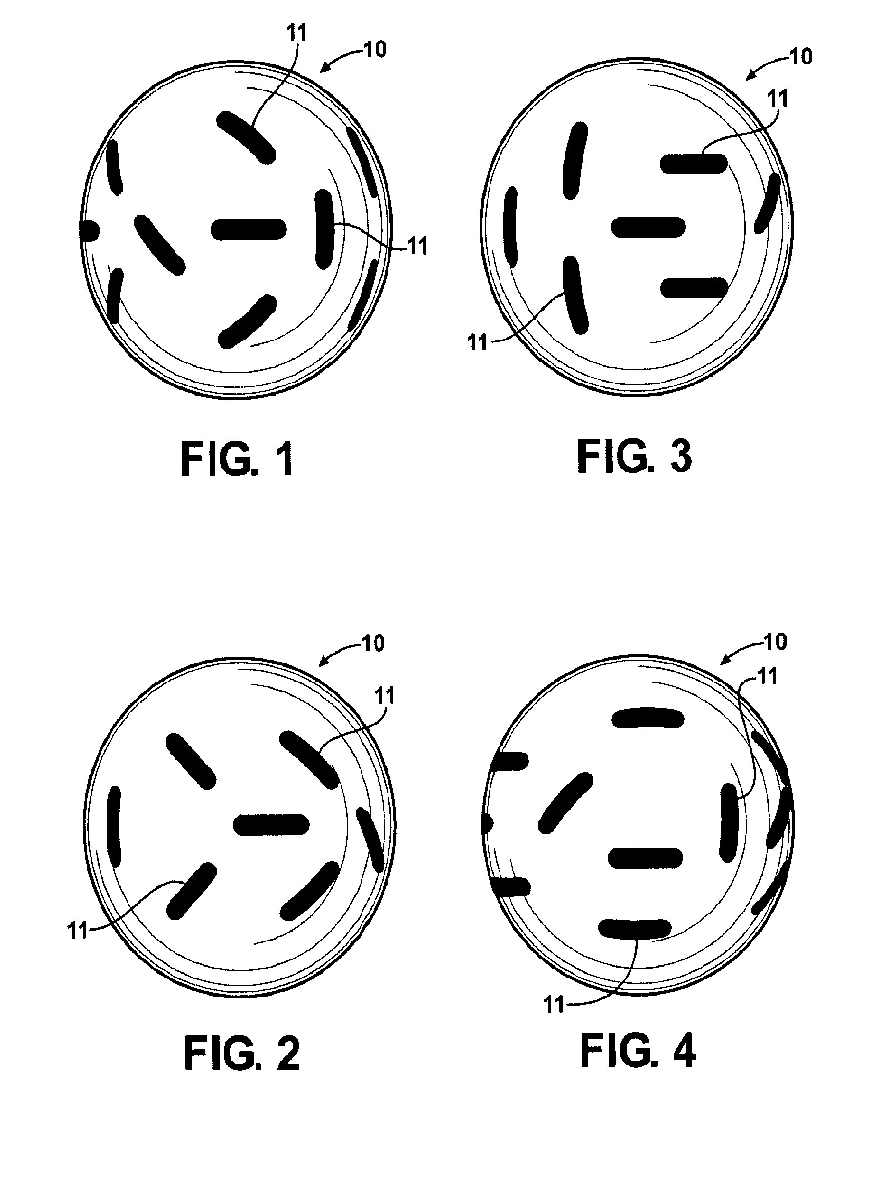
case 1
[0187] Marked ball with known model and 2 labeled observation sets. For two observations, the direct method is to calculate coordinate frames; Fc1, Fc2, based on the current set of fiducials (potentially including the ball center), and then using the same algorithm with the corresponding model fiducials calculate the model frames; Fm1, Fm2. Expressing the coordinate frames as matrices using homogeneous coordinates, we can calculate the offset matrices which will move the model to the observation positions by:
O1=Fc1*Fm1−1, O2=Fc2*Fm2−1 [0188]The desired offset matrix R, which rotates O1 into O2 can be found by:
R*O1=O2, R=O2*O1−1
R=Fc2*Fm2−1*Fm1*Fc1−1
[0189]If desired, the rotation matrix can be easily converted into equivalent angle and rotation axis formats using standard procedures.[0190]Quaternion format; (cos(⊖ / 2), ηx sin(⊖ / 2), ηy sin(⊖ / 2), ηz sin(⊖ / 2), or (angle, vector) format; (⊖, ηx, ηy, ηz).
[0191]Note that the angle is only known to a (+ / −) N*2π interval. The rotation rate c...
case 2
[0192] Marked ball with known model and N labeled observation sets. Any pair of observations will yield an angle / vector estimate using the procedure outlined in case 1. The vector estimates do not depend on 2 π intervals and a weighted average of the estimates can be directly computed. The average rotation rate calculation will depend upon finding the individual 2 π intervals that are consistent across observations as well as the assumed physical constraints. An alternate approach to finding the “best fitting” angle / vector is to set the problem up as a nonlinear error minimization problem of 3 variables, and then use standard techniques to solve for the unknowns. Multiple time intervals reduce the ambiguity and allows a solution even with rotations between observations greater than PI.
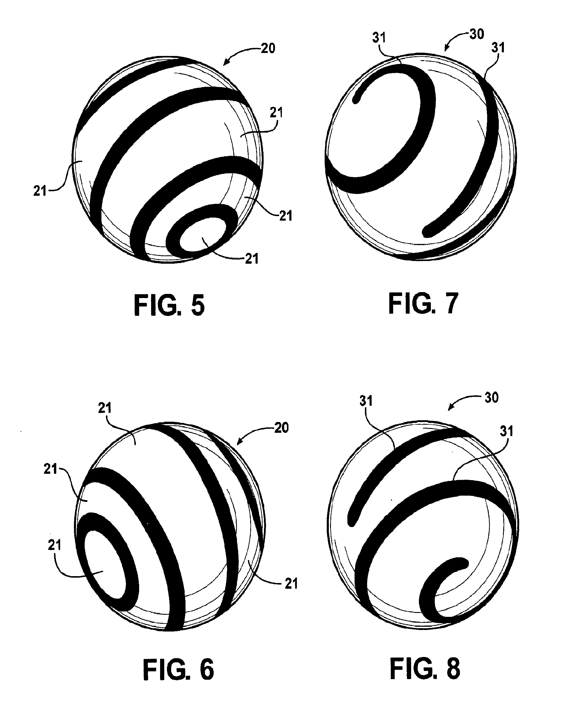
[0193]Logo Spin—For a known ball with identical marks on opposite sides of the ball then the spin rate and axis can be limited to a distinct set of possibilities. Note that in addition to positive iden...
case 3
[0194] Marked ball with unknown model and N observation sets. This technique requires common markings on the ball to be visible across multiple observations. The rotation of the markings will be perpendicular to the ball's rotation axis and the mark's displacement can be used to calculate a rotation rate.
[0195]Logo Spin—For an unknown ball the set of observations can be used to try to build a description of the ball consistent with typical marking of a ball. The known golf ball marking systems would be checked for consistency with the found observations and a model created if possible. However, if multiple observations exist which capture a mark or marks visible, then this can be used directly as above to find the rotation axis and rate, without building a model of the ball.
PUM
 Abstract
Description
Claims
Application Information